The first aim was to get the bike registered, so I was keen to keep any restoration work to an absolute minimum – especially since there was no italian logbook and I had never registered an imported vehicle before.
The to-do list was fairly minor, just re-commissioning, namely
- · Get it running
- · Sort electrics
- · New tyres
- · Check / service brakes
- · Registration
At no point was I going to undertake a full restoration. I was keen to keep the bike original, or as original as it was when it came to me.
Get it running
The engine wasn’t seized, had lots of compression and the gears selected – all very good news. There was no spark, and cleaning the points made no difference. The ignition coil was open circuit, but unsurprisingly a direct not available.
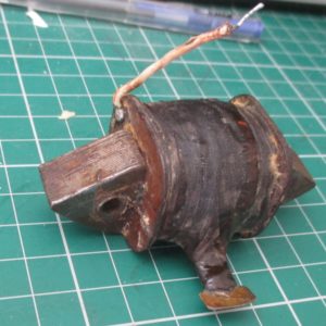
Some lambrettas use the filso magneto, and the hole spacing of Lambretta coil is very close, however the coil fouled the stator plate. To make life easier in the future, the stator plate was filed slightly, to receive the new, readily available coil.
The Lambretta coil has a slightly shorter HT contact, so was unable to use the existing Bakelite “distributor”. Attempting to remove this resulted in the distributor breaking, not surprising for thin, 60 year old Bakelite. I machined a nylon insulator, – with an M15x1 external thread, to fit into the crankcase. The centre hole was tapped to M4, to receive the conductor – this was a length of brass (approx 50mm long ), turned down and threaded to M4 (to accept a standard spark plug fitting), with a 6mm mushroom at the end (to touch the coil contact). The HT coil used a spark plug fitting at each end, a much better connection than the original “spike”. A HT distributor cap boot was fitted, to prevent water ingress
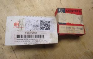
Whilst the flywheel was off, I fitted new points and a condenser. The condenser was awkward to find, as there are so many available. The correct one (20mm diameter) was found, manufactured by effe. The points are also similar to lambrettas – I used the pressed steel one, as the cast long arm points seem to be unavailable. These were an old stock part, as learning from the MZs, the older points are usually worth the extra cost.
With a new B6HS plug and a bit of fuel, the Iso started fairly easily. I timed it up (4.5mm btdc) with a strobe (the joys of having a flywheel!).
Electrics
Italian electrics seem to have a reputation; however, these didn’t seem too bad. Sure, an unregulated “6v” supply, from a 25W magneto to a set of bulbs whose sum power requirement is much greater does seem a bit old fashioned, but the bike is 60 years old.
Working from front to back, I started with the headlamp. The shell was full of questionable wire joints – where the insulation had been stripped, wires twisted together and finished off with tape. These were re-done, and despite the horror stories, the old wires had enough non-oxidised copper in them to solder. The old, pressed steel bulb holder was damaged, so I’ve replaced it with a CEV one from a lambreta.
There was no fuse on the bike, so I temporarily fitted an inline holder at the magneto end. This gave a more reliable and safer supply than the old twisted connections.
Next up was the brake light. This is the same as fitted to some of the Benellis – again a CEV item. This had been cut open at some point, so ideally a replacement is needed. However, I think a replacement cover is easy to make, when time permits. For the time being I used heatshrink to seal it up. The feed wire between the switch and light were open circuit – again thanks to dodgy connections, but a bit more soldering and a couple new wires were all that was needed to get the lights legal again.
The light switch appears to be different to the original factory one, however, it complements the bike well. The plastic base was held together with tape, so I machined a new one from a block of acrylic. A good soaking with WD40 got the contacts clean and temporarily put an end to the electric works. Going forward, I shall be fully re-wiring the bike, as it’s an easy task – 2 wires from the magneto, 2 to the tail light and 5 to the switch. I shall probably use modern thin wall cable; to reduce the two unsightly bunches of cables to the switch, down to one.
Tyres
The old tyres were well past their prime – quite possibly the original tyres – Ceat brand. The manual specifies 3.25×14 tyres, an obscure size, which only seems to be available from one seller in Italy. Instead, a metric 90/90-14 tyre seems to be a good alternative. I fitted a pair of Michelin City Pro’s, which, which admittedly are a modern tread pattern. However, I’d rather have good grip and handling than a tyre that looks nice.
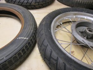
New tubes and a rim tape were fitted at the same time. A 16″ rim tape was cut and re-glued, as the commercially available 14″ tapes are too narrow.
Brakes
The brake actuator cams were cleaned and lubricated, and the glazing on the shoes removed. I intend to get them relined by Villiers Services in the future, once the logbook arrives.
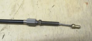
With my MZ, the front brake was terrible regardless of the type of friction material. Replacing the brake cable with a Venhill one gave outstanding results. I made a cable for the Iso from the Venhill Universal Clutch kit – which includes a 2mm inner cable, with a 7mm O/D Teflon lined outer. I made an adjuster, to take the larger diameter outer cable, reducing down to an M7x1.0 thread, to fit into the hub.
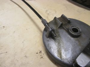
A standard barrel was soldered to one end, with a ball nipple at the other – the wire being splayed open prior to soldering. In all, a much better cable than the original – this had a tiny diameter inner cable, broken and rusted outer cable and a clamp nipple at the hub end.
Chassis
When I first checked the bike over, A stand-out issue was the shock absorber bushes weren’t there – the rubber had perished long ago. A new set was machined, with a 10mm ID central steel sleeve, inside a polyurethane bush. This was finished off with a pair of new bolts and thick washers (turned from steel bar, as commercially available M10 washers are never 10mm and are wafer thin).
The forks were fine; however the sliders were covered in grease. I cannot see that the forks have seals, so I have re-greased them, to see if any more leaks out. It is definitely something to keep an eye on.
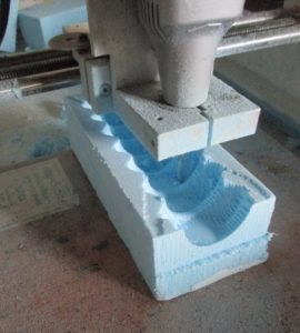
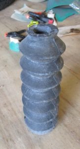
One of the fork gaiters had split in several places, so a replacement was needed. A steering rack boot from a VW golf does fit however is significantly longer than the original. Naturally, original Iso fork boots are nonexistent, so I intended to make one from RTV silicone.
The inner plug and outer moulds were drawn on CAD, converted to Gcode using deskproto and cut using my CNC router. I used blue foam throughout, not only to look after my cnc mill ends, but also so the internal plug can be dissolved away, once the silicone set .
The molds were covered in a film of mirrorglaze, despite instructions saying a release agent is not required.
To minimise air bubbles, I painted the RTV onto the moulds (both inner and outer) and then slowly poured in the mixture.
Unfortunately the mixture leaked out quicker than I could pour it in, so the whole mould was sealed externally with car body filler.
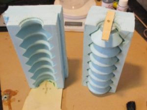
After a day curing, the outer mould was broken open, which required a significant amount of brute force, despite the release agent. In the end, I needed to sacrifice one outer mould, by clamping it up in a vice. Not the end of the world, as I had always expected the moulds to be single use.
The inner mould was removed by heating up the silicone in warm water, and flexing it over the mould, one segment at a time.
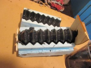
I was lucky – the gaiter came out in one piece, with no tears or air bubbles. It looks professional too – but was it really worth the dozens of hours it took to make? It’s not a particularly stand-out addition to the bike!
The fuel tank didn’t get much attention initially; however, keen to prevent any further rust, I removed the tank and cleaned off some of the flaky paint, on the underside.
As per the rest of the bike, I was not willing to paint the tank, so lacquered the bare metal areas, and waxoiled the underside (where the frame goes)
I did the usual trick of fill the tank with nuts, bolts and ball bearings, and shake to remove some of the rust. However, it was predominantly surface rust, so the tank was fairly clean.
The reason why the right hand tap didn’t work was because the gauze in the pickup tube (a spring) had dissolved over the years, and was completely blocking the tap. I removed the old tubes and replaced them with brass gauze, rolled into a tube, with a turned brass top and bottom, to push-fit into the taps.
The taps had been installed the wrong way round, so had required several fibre washers to get them to point the right direction, once tightened up. This did mean only 1 or 2 threads were securing the left tap. I had always thought they looked a bit odd.
I swapped them from side to side, meaning only a thin washer was needed to get the taps pointing the right way. Easiest job so far!
Registration
I sent over the required forms to the VMCC, before starting any of the mechanical work, to retrieve a dating certificate. After being inspected, a 1955 dating certificate was provided.
This was sent over to the DVLA, with yet more forms and the NOVA reference, and the logbook arrived in the post, 3 weeks later. Good news!