Sometimes its easy to forget how fortunate we are, with modern lighting in our cars – i.e headlights which actually emit light.
Luckily, the range of early MZ motorcycles are ideal for those wishing to experience riding in the dark . Anybody reading this far has found this page – probably by searching for “MZ 12v conversion”, so knows about the problem and can skip onto the next chaper
Whilst MZs (as a whole) are not bad at all, the early models are lacking in certain departments – most notably the 6v electrics. A fairly pathetic 60w (90w peak) dynamo, combined with a very basic mechanical regulator, results in a headlight which is about as effective as a glow-in-the-dark sticker.
But maybe I’m being a bit harsh. The dynamo is a robust unit, and I never had any major issues – other than night riding being a terrifying experience. There’s no reason why the original 6v system couldn’t be made to work, especially with LEDs and Halogen conversions available. However, a conversion to 12v seems to be the most logical upgrade. It gives far more flexibility, and swapping the headlamp reflector from the P45t to the H4 fitment means go-faster headlight bulbs can be fitted. Plus, any volts drop on a 6v is detrimental by the time it gets to the bulb, not so much an issue with 12v. And you can buy 12v bulbs without the guy at the motoring accessory store looking at you like you’re extra terrestrial
12v Conversions – the options
There are a few ways to get to 12v
Fit a 12v regulator – others have found that, by ditching the old mechanical regulator in favour of a 12v electronic regulator, the stock dynamo is able to produce 12v. This is by far the easiest way, but is not the best solution. You still only have a 6v, 60w dynamo – so I’m not convinced. I expect the output is still pretty dismal. Also, the dynamo will only produce 12v at higher revs.
Rewind the old dynamo. I looked at rewinding the original dynamo, so the engine doesn’t need to rev as much to produce 12v. The only possible way of doing this was to rewind the field windings on the stator, but I think there’s a lot more to it. Plus, in order to get the windings to physically fit on the poles, you’d have to use thinner wire – not ideal.
Buy the readily available aftermarket kit (I’m not naming names here). It’s a direct fitment, with everything wired up ready for assembly. Fit and forget. Job done. It uses electronic igntion, so no more setting points. I’ve got one on my TS – it’s great, but the pricing has put me off buying subsequent ones. Though I can now see how they got to that price. 2022 update. That was written in 2020. There are now two brands available that I know of. My personal experience has lead me to staying with 6v or my own system. However I’ve only tried the expensive system – not tried the other brand yet. Looks like a good kit, and doubt it would be £100 for a replacement coil like I was looking at
My method. Adapt a commercially available magneto (off a moped) to fit the TS case. This option gives CDI ignition and a 12v output. However it is far from a bolt-on option. The subsequent pages will describe the process I followed for making the conversion. It’s ideal for those who arent scared of the odd bit of machining. I am fortunate and have access to a good lathe and mill, allowing me to do these silly projects. There’s a lot of trial and error, and took two bank-holiday weekends (during the covid lockdown, before I started a new job) to get it to a stage where the bike runs.
Please note – the contents of this page is provided for personal non-commercial use only. Copyright applies. Also, please be aware that this is a DIY project, and I have only undertaken minimal testing. I cannot be held responsible for holes in pistons if the timing is wrong. There are aftermarket kits already available, so use them if in doubt. My intention is not to tread on anyone’s toes here, either – I am making no money by writing about my projects.
How to choose a magneto
You dont need to. Use a minarelli AM6 one. Skip to the next chapter, or if you want to know how I got to that decision, read on
If you do a quick search, for “stator flywheel”, on the polular auction site, you will notice there is a wide range of magnetos available. Some are as cheap as £14, some are not so cheap. They all vary – what we need is a flywheel / rotor with an outer diameter diameter of about 100mm, so it’ll fit in the footprint of the old dynamo.
Unfortunately, these kits are sold for specific bikes. So yes, the listing may say it fits a lifan 150, but what diameter is it? That means the only way of finding out is by buying it, or spending several hours researching each individual kit.
So, the first one I bought blind – in the hope it will fit. This was the cheap one, as fitted to chinese 125s and 150s. It didnt fit. Not suprising – sods law states that the £14 stator/flywheel kit is too large by only a few mm. These cheaper kits also have an external pickup sensor. In an ideal world, this would be desireable, however there simply isnt enough room in the TS 125 crankcase to house the pickup coil, let alone allow any adjustment.
Next purchase was a “performance kit”. These have a much smaller diameter (about 70mm), and the small size is marketed as a feature, as it allows the engine to rev easier. I dont really worry about revs, but the smaller diameter meant it was bound to fit. When it turned up, I wasnt convinced it was man-enough for use on a road bike. OK for a 50cc or a trials bike, but I wanted something a little more substancial.
Fast forward a year, and covid lockdown began. I was working from home, but lack of work meant I was sat doing very little other than exam revision. I split up revision with trying to find a stator. I had decided I wanted a stator with an internal pickup, so was able to come up with a shortlist bysearching for “stator” on the auction site. Then, eventually I found a suitable matching flywheel – off a minarelli AM6 engine.
This 50cc water cooled unit originally was fitted with a ducati magneto, but with cheap far-eastern copies available, a stator and flywheel kit was picked up for £70. For reference the AM6 was used on the earlier Aprilia RS50 and Derbi Senda.
The system uses a combined CDI/Coil unit, and a 4 pin regulator, making wiring very easy. The stator has 4 output wires – Earth, AC supply to coil, AC lighting output and Pickup sensor output. It’s all fairly straightforward.
How’s it done?
The AM6 generator does not fit directly onto the MZ engines – not even close. The stator backplate is too small, with the holes in the wrong place. The flywheel taper also is different, so the drive boss needs adjusting
Whilst the flywheel drive boss can* be modified to fit, there is no way of re-using the stator backplate. That goes in the bin and a new one is made from aluminium.
*If you’ve got the time and materials, a new flywheel boss is a good idea too – it’s a much better job. You’ll find out why later on
How I did it.
I did it the wrong way round.
I made the flywheel fit first, then made the backplate. Then I just ended up chasing my tail trying to get clearances to work. In the end the backplate was wafer thin, with the flywheel very close to the crankcase
The reason why I struggled initially, is because when cutting the flywheel taper, I removed too much material. So the trick is to make the stator backplate first, as thin as possible to keep a low profile, then machine the new flywheel taper gradually. Once you have a good taper, stop, otherwise the flywheel will rub on the crancase or stator if you remove too much material.
How should it be done
In an ideal world, a new flywheel boss should be made, then it doesnt matter how “high” the stator backplate is.
But machining a new boss from billet seems so wasteful – three quarters of the steel billet becomes swarf. Easiest way is to machine a low profile backplate, so the stator is as close to the crankcases as possible. Then the original flywheel boss can be adapted to suit the stator. It’s all very marginal – only a tiny bit of the original boss taper can be removed, so dont be suprised if you end up machining a new boss anyway.
Regardless of how you chose to do it (drive boss first, or backplate first), machining the backplate and adapting the boss follow the same process.
Machining the new backplate
I machined the backplate from a 4″(101.6mm) aluminium billet. I bought a 50mm length so I could do 2, but a 25mm length is probably better – it saves some interesting (scary) parting-off
Much of the dimensions can be taken from the original stator backplate – so dig that out of the bin.
First step is to machine the mounting boss. This is the “island” where the stator bolts on, so determine the diameter by measuring your stator. It’ll be about 38mm diameter. This wants to be about 9mm high, though keep it as low as possible, without the AC supply coil touching the back of the plate. If you’ll be making a new drive boss, this can be as high as you like, it’ll just mean the assembly is a bit further out, away from the crankcase.
On the top of the boss is a locating step, which will be the same diameter as the stator hole. This only needs to be about 1mm high – it’s just to hold the stator central.
Then take the plate back out of the lathe, reverse it and re-mount it in the chuck with the jaws on the mounting boss you just machined. Machine the external diameter, to suit the TS crancases (about 97mm) and machine the back. The back only wants to be about 3 or 4mm, and turn a recess (about 1.5mm deep) to clear the sealing ring cap.
Take your backplate and put it in a mill,with a rotary table or dividing head. Drill and tap the stator mounting bolts in the centre, and mill out the slots at a PCD to suit the TS mounting holes. I milled the slots by about 25 degrees, so that works out at about 10 degrees adjustment either way.
The locations of the slots should be such that, when mounted in the engine with the slots in the middle of adjustment, the pickup coil is at 9’oclock. Also make sure the stator poles do not foul the mouting holes.
Drill or file a suitable slot for the wires to exit.
Adapting the flywheel boss
Ideally you should make a new flywheel boss, but if not the boss can be adapted by removing it from the flywheel (by drilling out the rivets) and machining the new taper.
More to come soon.
2022 update. 18 months has passed since I wrote the above. Some things have changed. A new retailer is now selling kits at a much lower price, and I feel it offers excellent value for money. I expect my DIY kit would cost £100 in parts and materials, but would need a weekend to do the machining, and a week of evenings fitting it, setting the timing and finishing wiring. Ready-made aftermarket kit would be the way I’d convert to 12v now.
Plus my setup isnt without its flaws. To set the timing, the flywheel has to come off. As you’ll read in my TS 125 sport build log, the output isnt really high enough. You do also need to give it a good kick to get a large enough spark.
The TS 125 sport build log does go through the issues I had. Mostly trying to work out a suitable regulator
If you are still inerested in the DIY setup, I did an article in the “MZRider” magazine. Effectively the next steps are
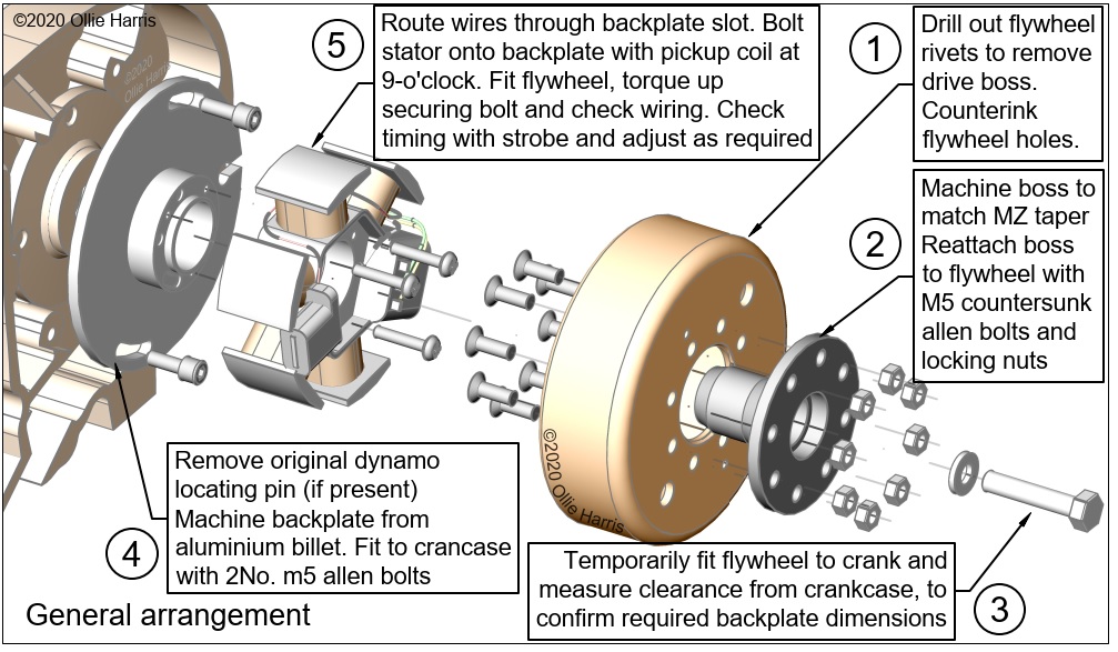
- Drill out the rivets holding the boss to the flywheel
- Knock out the boss and mount it in the lathe chuck. Set up the cross slide to match the MZ taper and machine a new taper in the boss. Bolt up the flywheel again using countersunk bolts (countersink the flywheel inner face)
- Find a new M7 bolt of the correct length to attach the flywheel
- Machine a thick washer to spread the load on the flywheel boss flange
- Fit the stator to the backplate. Bolt this to the crankcase. Fit the flywheel
- Wire up the original AM6 / derbi senda coil, as per their manuals.
- With a dial gauge, mark off TDC and the timing advance marks
- Start the bike, check the timing with a strobe. Adjust the timing by removing the flywheel, loosening the stator bolts and spinning it round. Retighten bolts, refit flywheel, try again. Should be 23degrees btdc approximately.
Apologies if anyone was looking to make this setup – most of the information is here now, but not to the level of detail I wanted. With another aftermarket kit available I dont see much logic in improving my setup
All images Copyright Ollie Harris 2020-2022