The engine rebuild is detailed here
Electrics
Since getting the bike registered, the wiring has mostly been full replaced. The new main lighting feed (from the magneto up to the headlight) was a worthwhile replacement. As part of the engine rebuild, I rewired the coil connections with silicone wire, as bare wires meant the spark and lighting output was shorting out.
A new 6v regulator was purchased, and fitted into the headlamp shell. This cuts off any voltage over 6v, which stopped bulbs blowing all the time
A quartz halogen headlight bulb means the headlight now emits some light.
Swing arm bushes
First a bit of background. Unlike some, I was anything but bored during lockdown in spring. I started a new job, just as the UK was placed into lockdown. Fortunately I had a fortnight’s holiday left over from my previous job, which gave me a bit of spare time. So the Iso then became the priority. Despite not needing a roadworthy test / MOT (as it’s over 40 years old), I think it’s essential for it to be to an MOT-worthy standard. This meant sorting out the play in the suspension. There was a small amount of play in the swing arm, which would be obvious to the MOT tester, and could even be felt whilst riding.
The Iso swing arm pivots on a 18mm shaft – effectively a long shank bolt, with a nut at the end. At the nut end (right hand side), the shaft has 2 flats, which prevent turning, and maintain the correct distance between the swing arm “forks” when the nut is tightened, so it wont just clamp up onto the frame.
The pivot is supported with two bronze bushes, which are a press fit into the tubes welded onto the frame. The whole setup is lubricated with grease, via a nipple on the top of the frame tube.
With the chain, rear wheel, shock absorbers and brake light switch removed, it is much easier to pivot the swing arm to check for smooth operation with minimal play. Most likely the bushes will need doing, after all these years.
First step is to undo the pivot nut, but remember to stop the shaft from pivoting, using a spanner at the other end. Dont do like I did and allow the shaft to turn. That hurt the oval hole in the swing arm, but not enough to stop it working. With the nut removed, the shaft should slide out, but take note of washers.
The bushes can be removed by hammering them out from the other side with a long drift. On mine they werent that tight, and came out with a bit of persuasion.
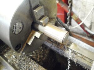
Measure up everything. In my case the shaft was quite worn (0.2mm undersize and not really round). Refitting 18mm bushes on the old shaft would be pretty pointless, so I machined down the shaft to 17.5mm. This also made sure the shaft was straight and round.
New bushes were machined from bronze hollow bar, with an undersized bore. The final bit would be removed later by reaming them in situ. They were parted off to length, slightly oversized initially, trial fitted, measured, removed and cut down further as required.
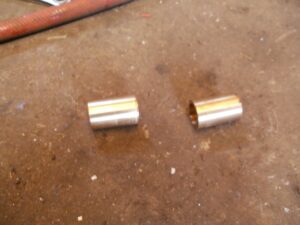
I dont have an oil groover machine, so had to resort to grinding the grooves by hand using a dremel type tool and a small rotary burr. It looked rubbish, but was functional, and only I know about it.
I matched the external diameter of the old bushes, but they were a very tight fit in the frame and initially I was using a draw bolt to force the first bush. I thought this was a bad idea. If I’m trying so hard to fit it, I’ll end up breaking something – either now during istallaton or if I need to remove them again.
So I removed the half-installed bush (easier said than done – that needed another puller, and made me panic a bit) and mounted it in the lathe on a mandrel. I skimmed off a small amount so the bushes would just push in, and refitted them with threadlock (which can be broken with heat, if I ever have to do them again).
Next step was to find a suitable reamer. Once you move away from whole-mm engineering tools, you fall into the industrial engineering bracket. So whilst a 18mm reamer is about £20, the one I wanted was over £100. Yes, the cheap reamers are cheap (say no more), and the >£100 reamer would outlast me, but I only needed to do 2 bushes. So I bought an adjustable reamer. The size I needed was a H7 – 21/32″ – 23/32″, which cost £12, and acutally wasnt that bad. Turned up very quickly too.
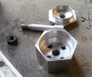
To ensure the bushes are absolutely parallel, I made a pilot which fitted to the end of the reamer. This was a length of mild steel, machined down to just over 15mm at one end, and the other end drilled and tapped to 1/2 bsf. This allowed the reamer to be mounted in the lathe, and the reduced-diameter section of the pilot to be machined down to 15mm, so the pilot was perfectly parallel to reamer.
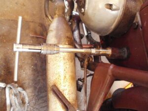
A temorary pilot bush was made up, to fit the inside of the swing arm bushes, and support the pilot.
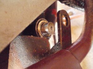
Only a small amount of material was removed at a time, until the shaft fitted nice. Because I had skimmed down the shaft, I needed to make a third bush to fit in the lh swing arm hole – at 18mm O/D and 17.5mm I/D it was quite thin!
With the nut and washer refitted, I had a good swing arm, which i promptly filled with a load of grease – shame it wasn’t done 50 years ago! On to the next task
Shock absorbers
Next, I got sidetracked and looked at the shock absorbers. The springs could be removed very easily (pull back the sleeve, pull out the half-round rings and the sleeves and springs just fall off). That gave me enough enthuisasm to rebuild the shocks
The shock absorbers were not great (you could say they were shocking). Going over a bump or pothole (yes, we have those in over here), would result in the bike bouncing down the road for a while. Horrible for me, funny for those watching in their cars. Also, the shrouds were stained with oil, and I sort of wanted to open them up anyway, to make sure all is good.
With the springs and shrouds removed, it was clear I needed new bump stops. The one I had looked like a slightly tapered cylinder, with a recess for the shock absorber top. So I made up a 3 piece mold on the lathe. This bolts together, and has 3 holes for filling it with resin.
Initially I used RTV silicone, but it was a bit too flexible. I tried some spare “PX90” polyurethane, but that was a bit too hard, so I bought some 60 Shore stuff, which was about right. The goldilocks story of the casting rubber resin world
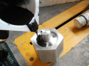
The resin is supposed to set in a vaccum, to remove air bubbles. I dont have that, so left it on top of the running air compressor – the shaking helps to remove the bubbles. Technical stuff
Wish I’d taken the second shock absorber apart beforehand, though. As itturns out this one hasnt been messed with, and had the original bump stop. This is a conical stop, which just sits inside the recess of the top spring mount – much simpler to make. Never mind
The shock absorbers were disassembled, using a tool made from steel flat plate, with two bolts fitted to act as pegs to remove the top cap. The cap was incredibly tight, and the body of the shock absorber needed heating until nearly red hot. Only then could the cap be removed
This heat wasnt an issue with the first shock, as it had no oil inside. However the second one needed to be drained out, via a hole in the bottom.
The piston, tube and upper tube cap could then be withdrawn as one assembly, with the lower tube cap left floating around at the bottom. The second shock was not so easy, as drilling the hole in the bottom introduced swarf, so the piston got stuck in the tube. In hindsight, I shoudnt have pumped up the shock to remove the oil quickly, as that must have moved the oil and swarf around inside, only to get stuck in the piston.
I drilled out the first shock absorber, and tapped them out to M3, to allow me to drain / refill them at a later date.
I then realised I needed a second type of bump stop (for when the shock is fully extended), which explains why they knocked when I’d put the bike on the stand. So a 2 piece mold was made, and new stops were cast as before.
The top caps were machined to accept a retro-fitted oil seal (10mm ID, 18mm OD, 4.5mm high). Plywood packing was used to protect the threads when in the chuck
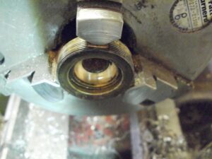
The oil seal was fitted with an aluminium mandrel, using red grease to help.
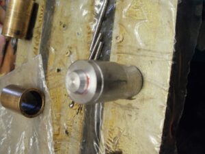
Mandrel for fitting the seal 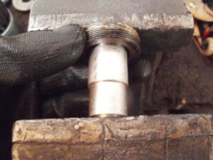
Fitting the seal using a vice
Having cleaned out all components (and lapping the tube on the second shock, to remove that swarf) the shock absorber was reassembled
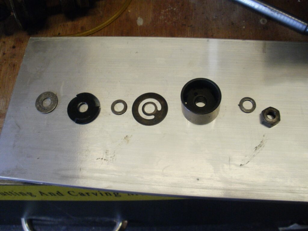
Piston / valve components 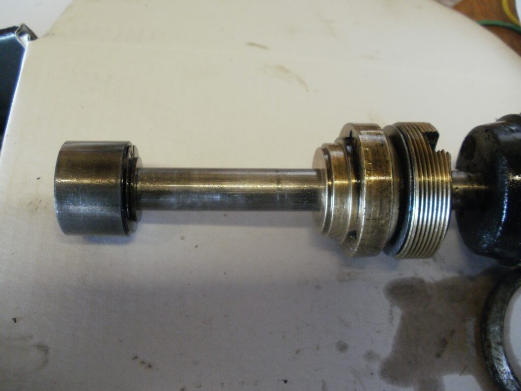
Piston attached to shaft, with top cap, tube cap and bumpstops fitted
The shocks were filled with 60ml of oil – just enough to reach the bottom of the piston when fully extended.
The top cap was refitted, and the spring, shroud and rretaining rings were reattached. That was the shock absorbers done – 5 weekends work to do these and the swing arm. Wish I’d never started!