August 2022 update. Note, this is no longer my bike (sold), though I have kept this page live for reference
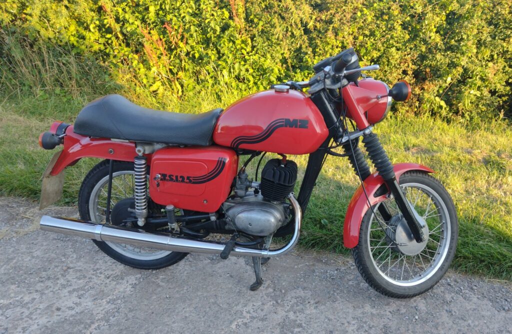
The TS 125 “sport” special, is a standard 1980s MZ TS 125, but with a custom seat, mudguard and tank, added by the MZ importer Wilf Green, in an attempt to modernise the styling and make the MZ more desirable. Aside from this, its a standard TS 125 – fitted with a 125cc 2 stroke piston-ported single engine, with a 4 speed box and 22mm carburettor. The frame is welded from steel pressings, with an aluminium rear subframe, with 35mm forks, and 18″ wheels
I cannot find much information online about the sports special, however, from a magazine review of the “pathfinder” (a trials version of the TS, offered by Wilf Green) it’s clear that this special edition was significantly more expensive than the standard TS – something which most likely also applied to the sports special, and may be why these are fairly sparse.
This page describes the rebuild of the TS 125. Generally follows a chronological order, split into 3 sections (as the project was somewhat “stop-start”). It’s a bit of a read, but may prove useful for anyone doing a rebuild – particularly if you use your web browsers “find” function to search for what you need – keyboard Ctrl+f on a windows machine
Any trade names / specific products are stated solely because it’s one I personally use and get on well with – I’m not affliliated to the brands. Conversely there’s no “brand bashing” here either, though if you wish to have a tradename removed please contact me.
Please note, like everything on the internet, it is up to the reader to do their own research beyond what is in front of them. I will not and can not be held liable for any damage/loss as a result of anything written below. The MZs have the advantage of the original service manuals being readily available. I follow those to the letter.
2014
In the case of this bike, I bought it at an auto jumble in 2014, and it was partially dismantled to load into the car. The engine was seized, as were the brakes, with the usual MZ rust (surface rust on the panels, frame etc). Being a basket case, once home, it was decided to fully restore the bike, so it was stripped fully (also to save room in the shed). The frame was sent off for powdercoating, and the panels were sprayed in 2 pack paint. The fork seals were then replaced, and if I remember correctly, serviced with new sealing rings / valve washers etc. New steering head bearings were installed
As with many projects, I find a small snag is enough to lose enthusiasm, fatal when I have so many projects on the go. In this case, the battery tray I fabricated (to replace the rusty one, and permit fitment of the better, but longer, “cyclon” batteries) did not have the side panel bracket, and would foul the rear tyre. This meant cutting into the nice new powdercoating, so it got put in the corner of the shed.
In the interim I fitted new swing arm bushes, but 6 years had passed until I got the frame back out again. In spring 2021, in between work and after Uni exams, I had a sudden burst of enthusiasm to sort 2 other MZ TS’s, both of which are dismantled. Whilst I was repairing the battery trays on these frames (correct dimensions this time!!) I sorted out the sports special frame, allowing me to proceed with the rebuild. Up to then, I hadn’t taken any photos of the process, so really the build log starts with a good chunk of the work done
2021
Engine
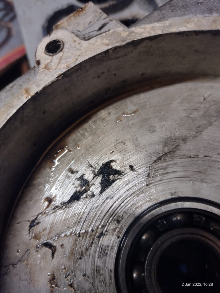
Early on in my ownership, the barrel was removed to investigate the cause of the seizure. The piston was rusted in the bore, and upon removal of the barrel (with gentle encouragement), the skirt of the liner broke. At this point it became clear that the cylinder had been overbored, to what looked like a 160cc capacity. It was certainly larger than a 150 bore. It is unknown what caused the seizure – perhaps the thin bore had cracked before being laid up. What I do know is that there had been water ingress, as the crank was rusty, with a clear tide mark on the crankcase.
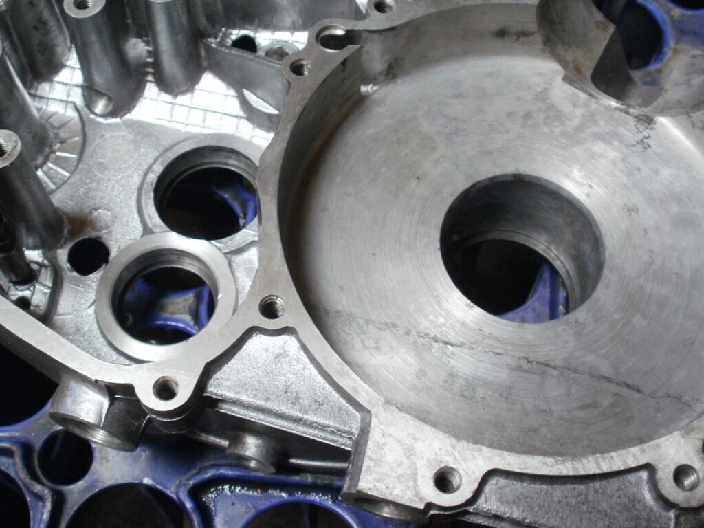
Fortunately, the water damage was limited to just the crankshaft, with no rust in the gearbox.
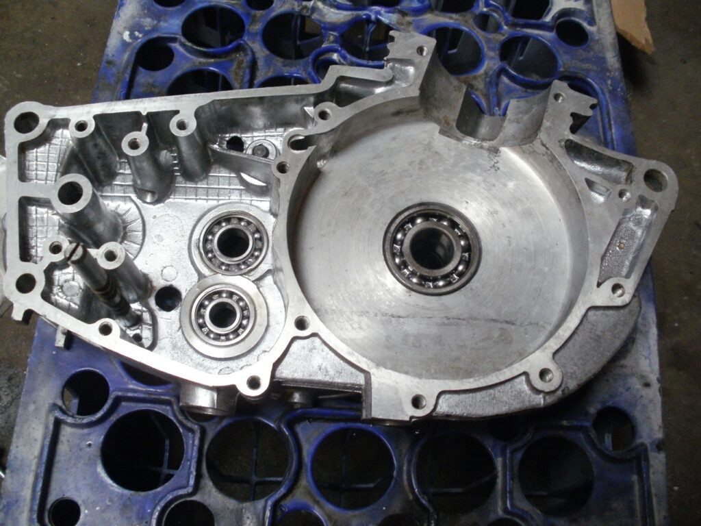
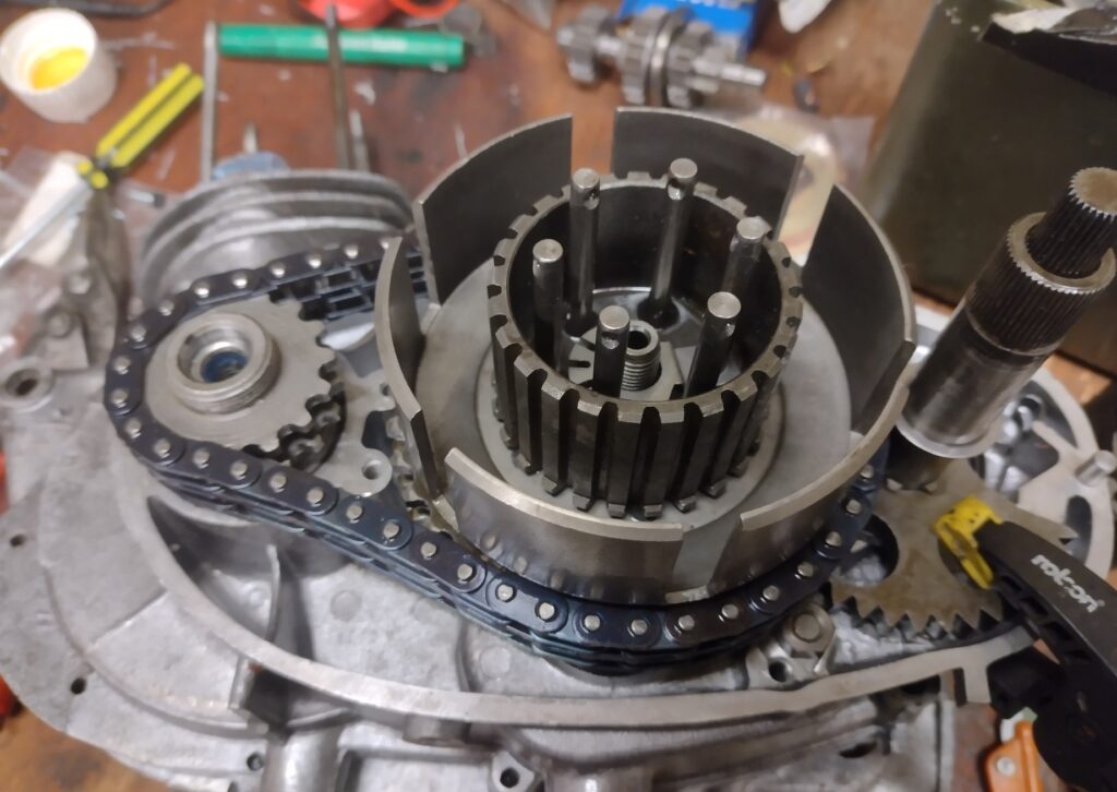
Once the primary drive had been removed, the presence of the original MZ screws, retained with that yellow shellac-like sealant, suggests the engine might not have been apart many times, if at all. Splitting the crankcases revealed it was all clean inside, with minimal wear on the gears and gearchange. The gearchange return spring was replaced, as a matter of course. I’m still not convinced – one would argue that the genuine MZ spring may well be better than the aftermarket one, seeing as quality of new bits nowadays seems to be variable at best.
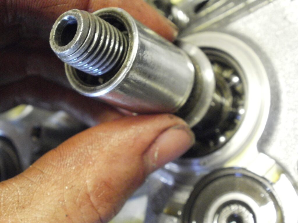
The layshaft bush was serviceable, so wasn’t replaced. SKF bearings, of the correct type and clearance replaced the old East German DDF ones, which especially in the case of the gearbox output bearing were well overdue replacement.
A replacement crank was rebuilt with a new conrod. The gearbox was adjusted as per the manual. The crankcases were joined with Dirko sealant, new bolts fitted and everything turned perfectly smooth without having to resort to “adjusting” the crank with a hammer!
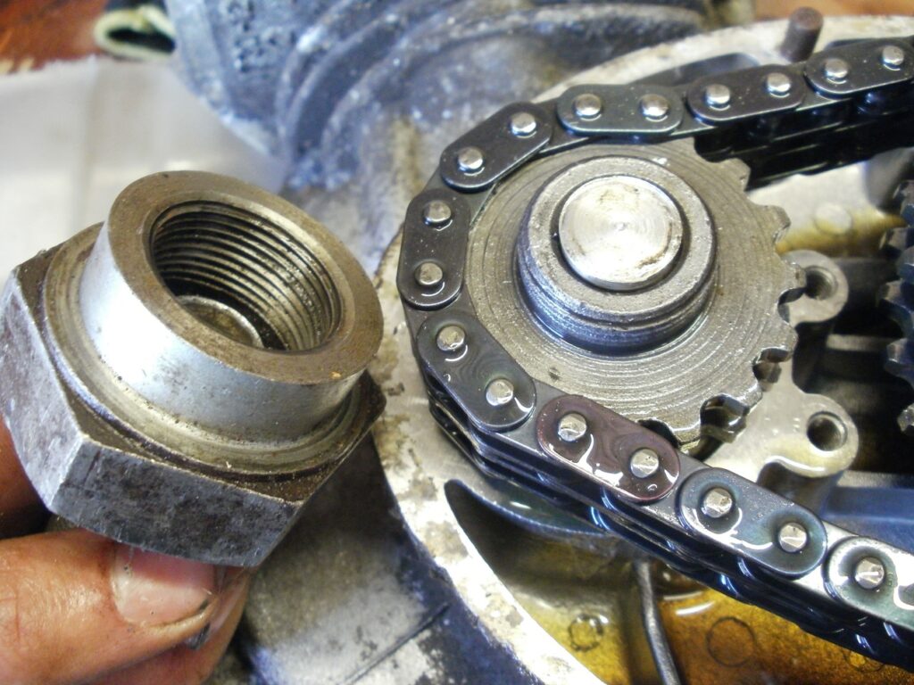
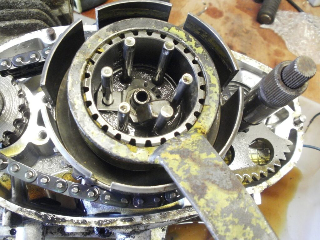
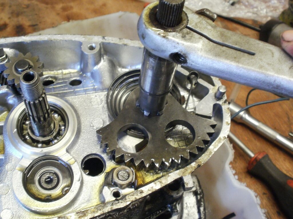
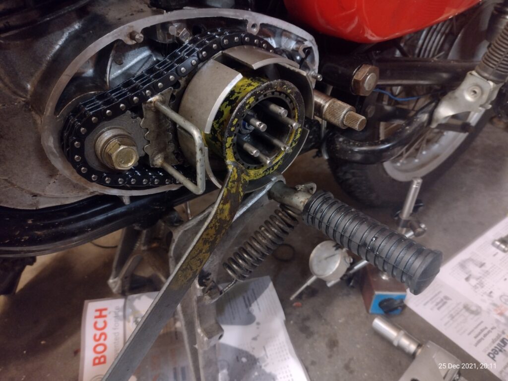
The rest of the rebuild continued, checking all parts for damage and wear. The primary drive appeared to have minimal or no wear, however the kickstart quadrant was replaced with a NOS item, and the ratchet gear, on the rear of the clutch basket replaced with a better used one. A fairly common fault with the TS is a locking kickstart lever, where rather than engaging and rotating the clutch, it jams. This can be caused by damaged teeth on the quadrant, which seems to, in turn, destroy the pinion – most likely caused by aggressive kicking, without gently engaging the quadrant beforehand.
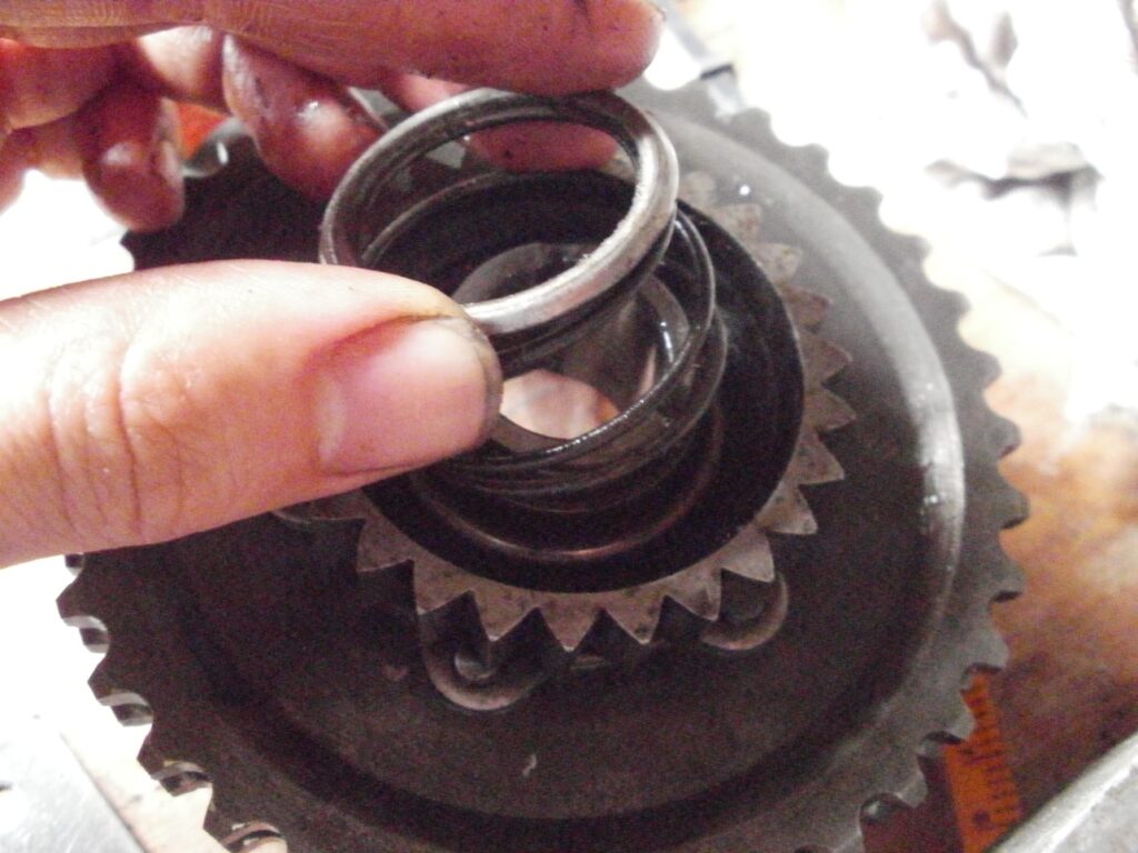
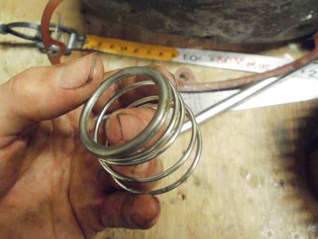
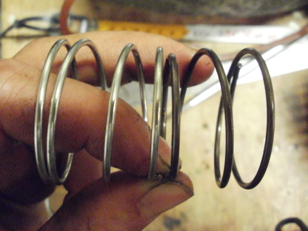
Another fault with the TS is the kickstart pinion coming away from the clutch basket, due to the spring or retaining ring failing. This results in a ratcheting noise, even with the kickstart disengaged. The aim was to replace the spring, ring and circlip, however yet again the quality of aftermarket parts let me down. The new spring was too big for the retaining ring, and did not seat properly. So I retained the original spring, but replaced the circlip and ring.
Both sealing caps on the right hand side were shimmed up, with new seals and homemade gaskets fitted (some of the aftermarket gaskets are made from cornflake packets, whereas I like proper gasket paper). If anyone ever needs some nice gaskets, I have a stock of NOS MZ ones, and also a lot of the TS 125 gaskets “on file”, ready to cut out with my laser cutter
Since the original top end had been overbored and subsequently damaged (possibly by me, but the piston had to come out somehow, and the hammer/block of wood was a last resort) a replacement used barrel and piston was fitted. The barrel still had the criss-cross pattern on the bore, as I had recently had it rebored for my other TS. I ran this barrel (and its Almot piston) for a couple hundred miles, just to try something out on that bike, then swapped barrels again – so I had a barrel in stock with a recent rebore – seemed sensible to use that on the Sport. Other than being sprayed with high-temp black paint, it’s a standard barrel and piston – proving the “sport” term is nothing more than a marketing ploy!
The cylinder head nuts used on the MZs from standard are of a higher grade steel than standard nuts, as one would find out if standard nuts are tightened to the specified torque. There’s a terrible sinking feeling when you feel a thread strip, though fortunately when it happened to me years back, it was the nuts stripping and not the studs being pulled from the block. Since then I have used studding joiners instead of standard nuts – these are used to join studded bar together, and are effectively a very tall nut. Thankfully MZ use standard metric threads on all nuts and bolts, so M6 stud joiners are readily available. Only issue is, some method of spreading the load is required, and there’s only minimal amount of spare thread protruding from the head, so I machine a shoulder on the nuts to accept a thick washer. This maximises the amount of threads, whilst allowing a really thick washer to prevent cutting into the soft cylinder head.
Frame
Next bit was finishing the rolling chassis. I had already previously rebuilt the forks, so they were assembled in the yoke, and it was just a case of tightening it all up. Before this build log, I had also replaced the swing arm rubber bushes, so all that was left to do was to refit the pivot and tighten it all up. Replacing the swing arm bushes is not a job for the faint-hearted, and I’d recommend, unless they are seriously perished, leaving the originals in place.
The alloy seat carrier was cleaned but not polished, and refitted with the old bolts (as apparently the bolts are of a precise diameter, to suit the frame). I did find a nice old stock (but shop soiled) coil bracket in the spares pile, so on it went. The nuts were glued and torque up to 50nm – as the workshop manual does warn of loose bolts causing handling issues. I used the right hand side panel to line up the bracket correctly; though I’m sure in the factory they probably had a jig
There are 2 lengths of MZ shocks, and the nice new old stock ones I had were the longer items, as fitted to the ETZs (I think). The TS125 uses the shorter ones, and the old ones were rusty. I had a couple of new shock absorbers in stock, but like so much of the aftermarket stuff, the quality control is occasionally poor. In this case, the bore of the spring adjusters was too large, so I replaced them with old MZ adjusters, giving me a set of reasonable shocks. I machined up some new washers to fit the shocks, as standard penny washers are really too thin in my opinion
At this stage of the rebuild, I needed to make a decision. As I found with the shocks, a lot of the stuff in the shed was of useable condition, but not shiny and new. I had the same issue with the chain adjusters, and the cost in the UK was far higher than the German retailers. In fear of the bike becoming an endless money pit, I decided that I’d build the bike with the best stuff in the shed, and avoid buying things where necessary. That helped the process along, and helped my wallet.
I didn’t go mad with polishing the rims, they only got a clean, and I don’t think super-polished alloy looks right on an MZ. I fitted Metzeler me22 tyres and Michelin tubes. I found the ME22 tyres a really good match for the MZ 125 – though they don’t last too long especially the rear, it’s not such a problem on this bike as I don’t plan to commute with it.
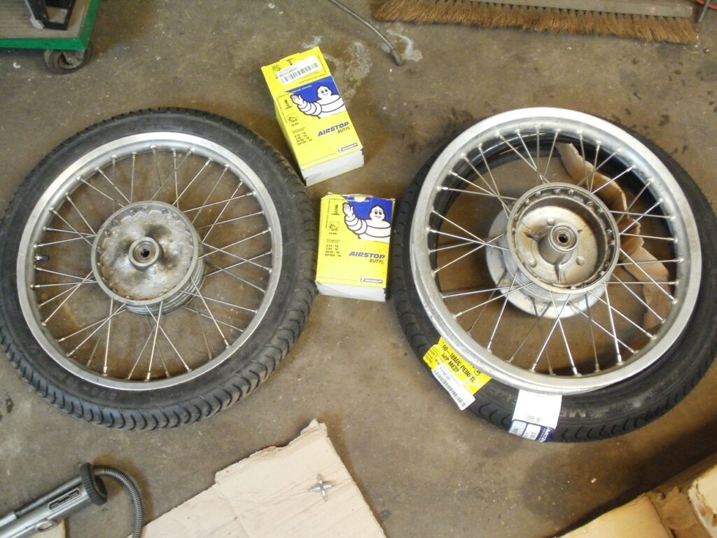
The hubs were fitted with new wheel bearings – as always a brand name, but I can’t remember the exact brand – NSK I think
The brake backplate went for a swim in the ultrasonic cleaner, then were fitted with new EBC shoes on the front, and original MZ NOS shoes on the back (I read somewhere that the original reddish compound from MZ works well, but wasn’t confident with fitting old stock shoes at the front). The front shoes were skimmed round in the lathe, to match the hub diameter better.
New brake cables were fitted, with a nylon-lined Venhill at the front and an old stock MZ one at the back.
I only had second hand handlebars, which all had a bit of rust, so I chose the best one. Though like many of the used parts I fitted, it won’t take long to replace, and I couldn’t justify the cost at the time. It is badly pitted, but an original item which is better quality than the aftermarket ones. The remainder of the handlebar was a selection of new old stock and good used items. My only regret is not buying the switchgear gaitors. Instead I made one from silicone which has since split. Replacements are in order
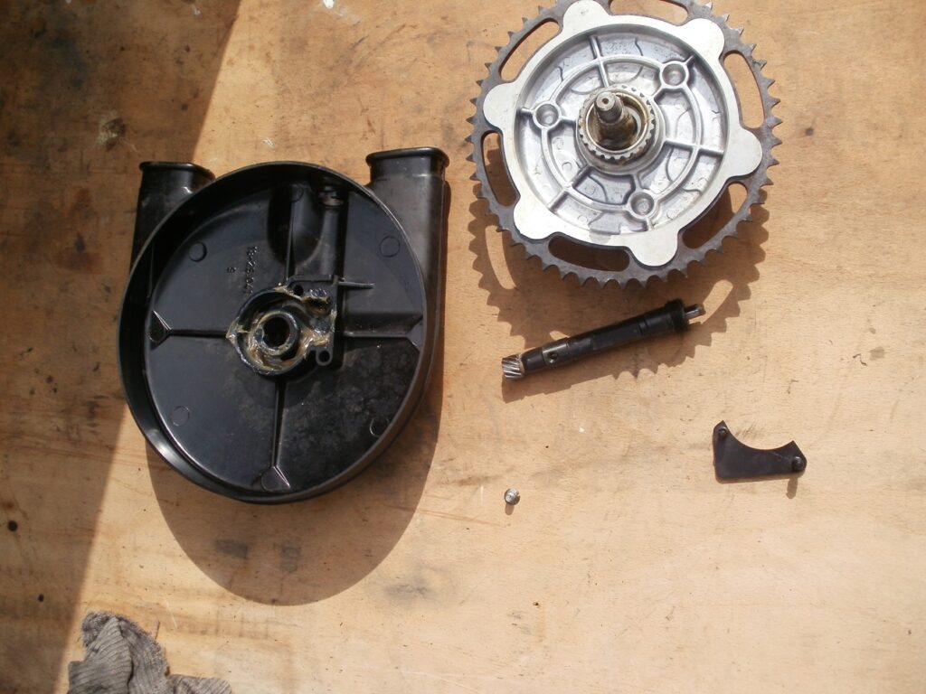
I found out the least-worn rear sprocket from the shed and a nice, undamaged sprocket cover. Gave it a good clean and packed it with new grease. I also fitted a new carrier bearing. I had a pair of old stock rubber chain gaiters (the new gaitors are rubbish, and the cheap new covers do not fit well), so they went on as well, packed with a large proportion of a canisters worth of grease
I found out some good second hand footrests, foot pedals and brake torque rods, which gave me a finished rolling chassis. I re-bushed an old side stand, and fitted a new high tensile bolt. The whole assembly was painted with hammerite
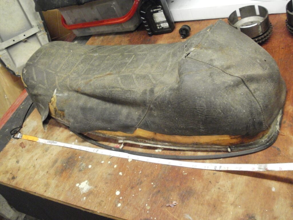
The seat was in poor condition, so any work I did on it would be an improvement. Clearly it had been sat in the sun for many years and had dried out and cracked. What was left was just fragments of the original seat cover. Being a special edition, the standard TS cover does not fit. Instead I believe it’s an aftermarket Giuliari seat cover, seemingly destined for a Honda 400/4, which had two additional sewn joins, to shorten the “hump” at the back. That’s all I could fathom from an internet search, as I can be pretty certain Mr Green did not get the tooling made up to heat-press the cross hatching on the top of the seat. I saw one on these seats at an auto jumble, and it was exactly the same pattern as the sport.
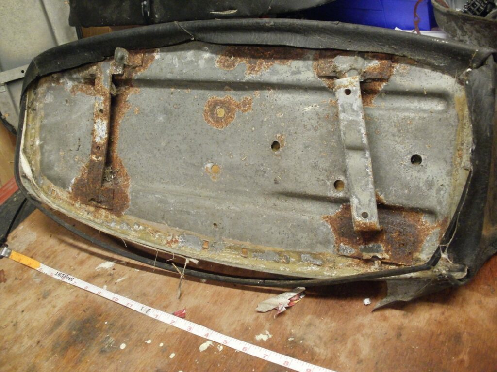
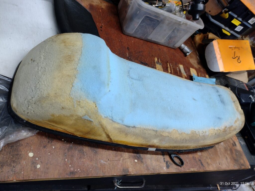
Anyway, these seat covers are no longer available, so I sent it off to a well known cover manufacturer, who did a brilliant job at a very reasonable price. Considering the old seat cover was in a terrible state, it fitted very well. The set foam had a huge slit in it, which had been filled with foam. My guess is that the foam base was also an aftermarket item, from another bike, and the slit was added to get it to the correct width for the MZ base (A new old stock base was used). The foam in the slit had sunken, and it was obvious when I fitted the cover, so I added a thin section of firm foam to the top. I thought I shaped this fairly smooth, however lateral lines can be seen under the cover, where I shaped the foam with a hot wire. Really this needs to be redone with a palm sander. Fortunately I didn’t glue the seat cover on, so can be done easily once the bike is on the road.
Before going to paint, I took a tracing of the tank and side panel decals, along with loads of notes and measurements. In fact, I even set up a grid on the tank, and took coordinates, so I could match the original pinstripes. I drew up the markings in CAD and fitted the new vinyl stencils on the nicely painted panels. It looked really smart
The front mudguard, it now appears, is the wrong one for the bike. It is off some Japanese trials bike, which explains the spacers required to get it to fit. I only realised this once the paint was done. Fortunately I have some spare paint and a mudguard, but I don’t mind the plastic one currently fitted.
The tank was fitted to the frame however the standard rubber mounting bobbins were too low to support the tank. Therefore new ones wer cast from polyurethane casting resing, and the mold which I made for my Iso’s shock absorbers. Works well.
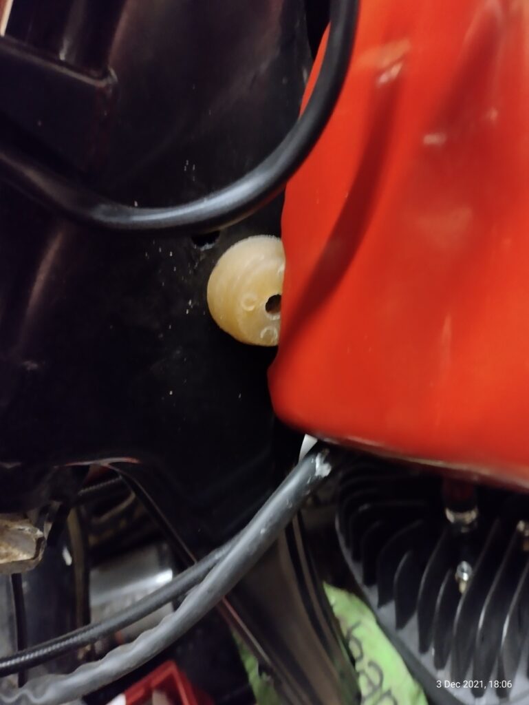
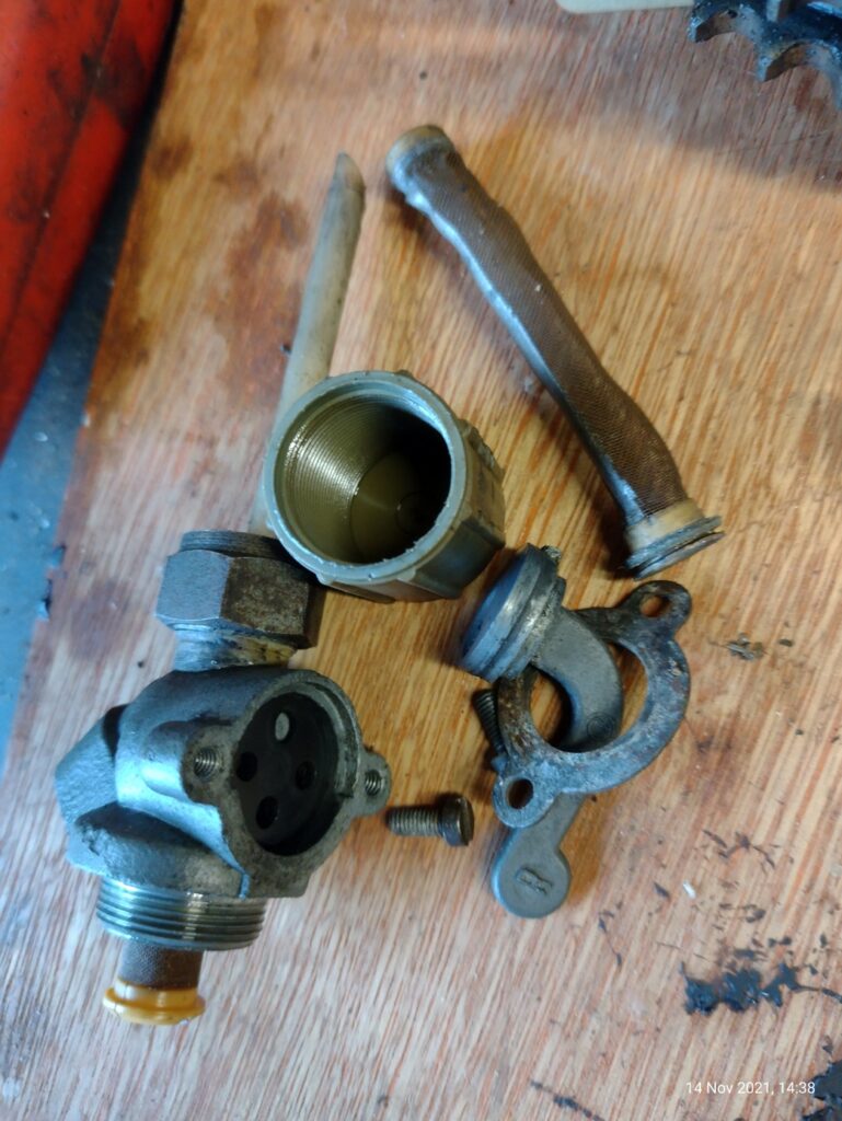
The fuel cock was cleaned in the ultrasound cleaner, and a new old stock fuel strainer added. I made a tap seal from Viton rubber, in the hope it will be more resistant to ethanol. It’s been in there for 4 months now, with no sign of leakage at the time of writing.
Wiring
I decided early on that the bike would be 12v. There is nothing wrong with the 6V dynamo, but 12 does give more flexibility with bulb choice, especially for the headlight where I normally fit a Phillips Nightvision, and a Wipac Quadoptic reflector (which do give more light).
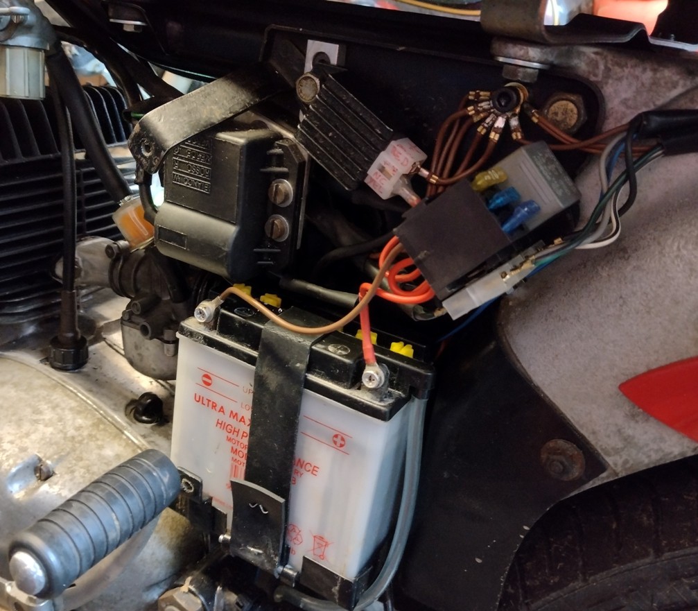
In this case, I fitted my DIY conversion, which uses the ignition system off an AM6 engine (e.g. Derbi Senda or Aprillia RS50), along with a homemade backplate. The regulator and coil are slightly smaller than the MZ components, so fit neatly under the left hand cover. I made up a bracket from aluminium plate to secure the coil, whilst avoiding any un-reversible modifications to the original mounting bracket.
The ignition system has a relay, so this needed to be mounted neatly and securely. For this, I found a socket which incorporated 3 fuseholder. Excellent, as I always like to run a third fuse.
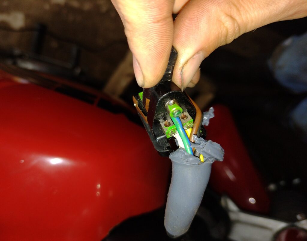
I couldn’t find the original wiring loom, which possibly is a blessing in disguise. There’s nothing wrong with MZ wiring, but after 30 years the contacts are more than likely corroded. On my other TS, it would be no exaggeration to say every terminal has needed a clean or replacement. So I bought in a load of cable, sleeving and terminals and soldered up a replacement loom.
I’m no wiring expert, so the wiring in the headlamp was somewhat of a rats nest, but just as tidy as if I bought a loom.
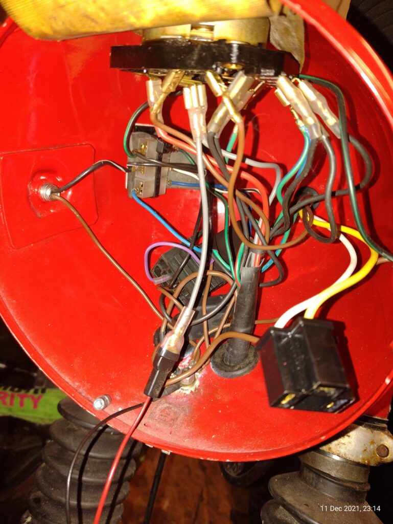
The availability of standard wall cable has dwindled in recent year, with thinwall cable being much more readily available. So certain colours of wire (in particular for the indicators) had to be altered from the original MZ scheme. However hopefully the use of a connector block under the left side panel should help with fault finding (normally bullet connectors are used, and it can become a bit of a rat’s nest in this area on the 6v system)
On the 6v system, a bulb (in the speedo) lights up when the battery voltage is higher than the dynamo output voltage – indicating a lack of dynamo output. It also doubles as an indicator warning light. Being a magneto-type generator, I could see no easy way of incorporating the original charge warning light, so opted to have this light as a indicator warning light only. This required a 4-pin flasher relay, which has a separate connection for the warning light. Supposedly this was an electronic relay, allowing fitment of LED lights, however upon connecting the LEDs, the relay didn’t work or at best it wouldn’t flash at a consistent rate. So, I went back to filament bulbs in the indicators.
The indicator wiring was put on hold whilst I sorted the read mudguard. This is a custom glass fibre moulding, which wasn’t a particularly good fit on the bike. The holes had been drilled oversized and out of alignment. I wasn’t keen on re-drilling the holes, so bolted it back together exactly as it came apart. The rear mudguard is slightly wonky, but not really noticeable until you look. I used done nuts to secure the moulding to the alloy sub frame, in which the right bolt also supports the silencer stay. I could see no way of attaching the stay to the outside of the fibreglass mudguard without damaging the paint, so is sandwiched between that and the ally subframe. I think that was how it was before, as the glass fibre mudguard is significantly wider than the subframe.
The rear light could then be fitted, and I had an old stock one on the shelf. This needed another hole drilled for the cabling, as the one on the mudguard was on the opposite side. I still need to add a blanking plug to the other unused entry.
I carried on wiring the rear section, fitting several new old stock bits such as a rear light lens and indicator bracket.
Final bits
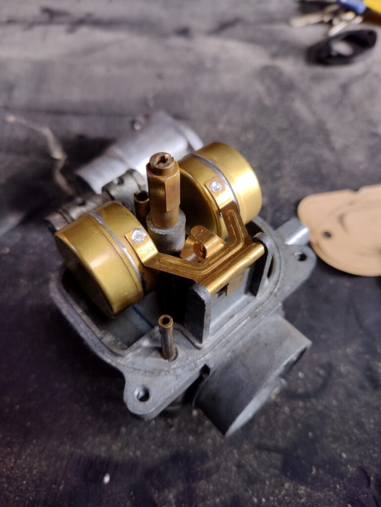
With the wiring complete, it was on with the carburettor. The bike is fitted with a standard BVF carb. This is of the later type by standard, which has the throttle stop screw. I ran this through my new ultrasonic cleaner, and fitted with new floats and float valve. For some reason, nearly all of the carbs I’ve seen have mangled heads on the float bowl screws, so I replaced those, as well as fitting a new bowl gasket. I set it to the standard settings as per the manual, being quite conservative with the needle position to ensure the newly rebuild engine is run rich initially. New old stock choke and throttle cables were fitted.
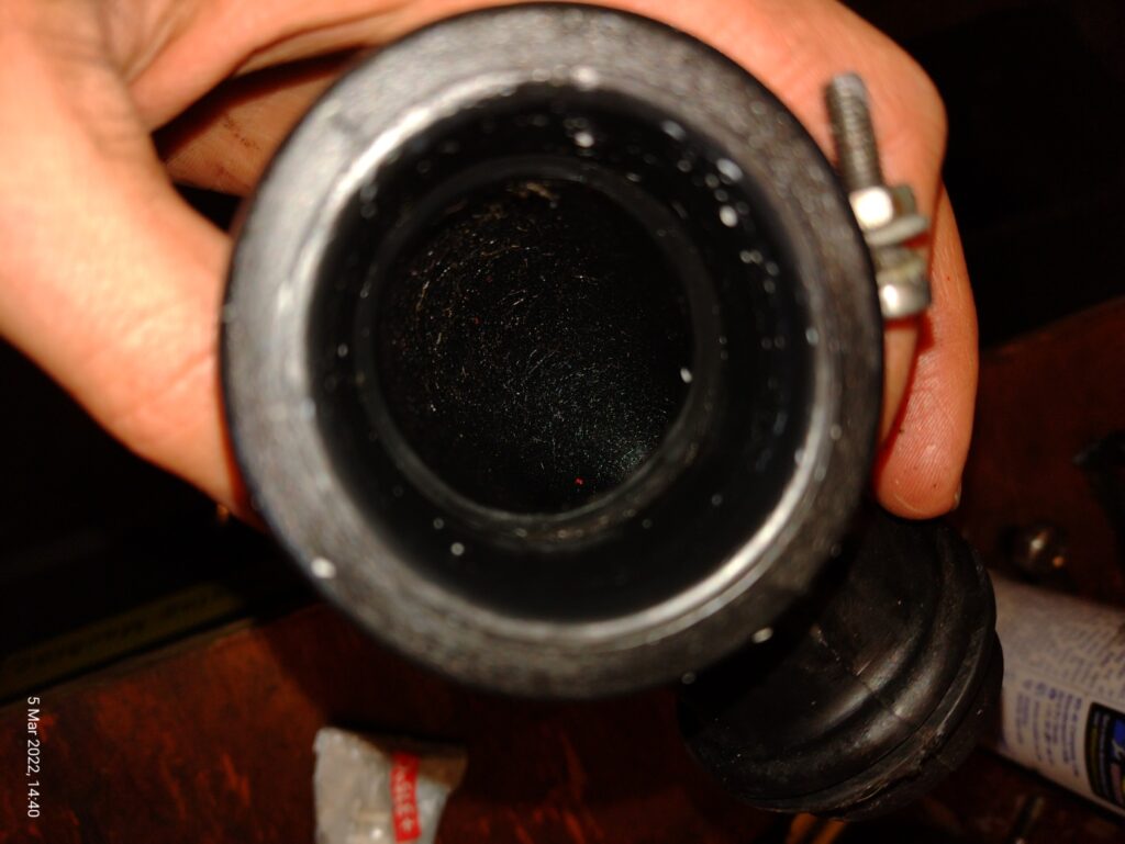
Initially a small 3Ah battery was fitted, whereas the tray is large enough for a YB5L-b battery, which is a good replacement for the 6N11A-4 which one would use for a 6v system (very similar dimensions). A new air filter was added, as well as a new old stock intake rubber. The right side panel had to be fitted with a bolt and nut on the rear mounting, as the threads had previously been stripped. This allowed me to fit a double height locknut, which had a grove in it for a length of wire, which acted as a tether to attach the toolbox lid. These have a habit of falling off, so the tether should stop it from being lost.
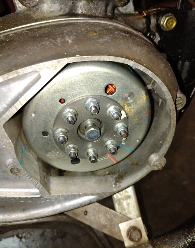
With 450ml of oil (some use silkolene light gear oil, as it reduces clutch drag – I’ve never had much of an issue, so use bog standard ep80/90 gear oil. It’s important to ensure the oil is compatable with “yellow metals” as the MZ uses a bush for the layshaft. GL5 should be avoided unless it says it’s otherwise safe for yellow metals) I attempted to start the engine and it started quite easily. That said it was gutless and wouldn’t rev, so clearly the timing was off significantly. Being a magneto/flywheel setup there’s no way to check the timing without the engine running, unlike the 6v system. I marked top dead centre and the 2 upper and lower limits for advance (2.5mm BTDC to 3mm BTDC as per the manual) on the flywheel for reference, using a dial gauge in the bore. I ran the bike and using a strobe checked the timing. As expected, it was very retarded, by about 10 degrees! So I removed the flywheel with the correct puller (and an aluminium spacer insert to protect the crank) and rotated the backplate anticlockwise (opposite to crank rotation) to advance it up. After a couple of attempts I had it within the 22˚45’ to 23˚45’ (between 22degrees45 minutes and 23degrees45minutes, if the format doesnt display correctly, or simply 2.5-3mm BTDC) range as specified in the manual, if a little retarded still.
The regulator I had bought was one fitted to modern mopeds, to match the AM6 stator which I had used for the 12v conversion. There was a bit uncertainty as to whether the AM6 regulator has a combined rectifier, as some diagrams show a single box for both regulation and rectification. However the workshop manual specifies a separate rectifier. It turns out the regulator only regulates (surprise!) and as a result, when the battery was connected, the fuse blew. I can only assume the battery fed backwards through the regulator to try and turn the charging coil into an electromagnet. Fortunately no damage was done, thanks to the very low rated fuse.
I tried a separate rectifier (just two contacts of a bridge rectifier), and checked the voltage across the battery to see if it was charging – it was producing an output, but it was quite disappointing – using a 50/55w headlight bulb meant the stator couldn’t keep up with draw.
As a result, I fitted a different regulator/rectifier unit, which resulted in a neat solution, however initially got the wiring wrong. Most mopeds have a headlight circuit (and charging coil on the stator) separate to the rest. This means the regulator has 4 pins – A ground, a supply from the DC charging coil, an output to the battery, and an AC regulator. The latter simply dumps excess voltage from the stator to earth. I had used the wrong terminal, and was attempting to charge the battery with the AC terminal, which without any feed just gave zero volts. D’oh. Easily done, as there are so many variants of regulators and stators, with poor instructions and no markings being the only thing they have in common!
With the rectifier/regulator unit correctly wired, it was now charging. It still couldn’t keep up with the big headlight bulb, so a lower wattage one was fitted instead. I might be tempted to fit a Tezet kit – they appeared on the market about the same time as I finished my DIY system. These are 3 phase kits and appear to be a much better solution than mine. If only I had waited a few weeks! I would’ve bought one instead of making my own had I known – they look like good kits and I’ve heard good things
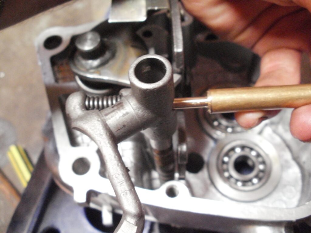
Next up was the MOT. The ride there and back was mostly OK; however there was a rattling noise from the primary drive. If I was to worry about every noise from an MZ’ I’d be rebuilding them every journey! However this one was a bit of a worry. Fortunately the bike passed the MOT, and the rattling noise abated by the time I got home. Third gear was an issue, so I removed the primary drive and tried adjusting the detent pin, using an endoscope through one of the crankcase holes to inspect the clearance on the layshaft and mainshaft when in top gear. With it readjusted I was hoping it would stop jumping out of gear.
2022
I took the bike along to a new years day bike meet at Bitton railway station. Arguably one of the nicest events of the year, at a time of year when nothing happens, at a nice venue fairly close to home – Ideal for a newly rebuilt bike. Some interesting bikes always turn up. The previous event, I pushed my Iso there (it overheated and boiled the carb). Fortunately the MZ got there on its own steam. At the time I had the bike up for sale, as I considered to too good to sit in the damp shed, and be abused by me for commuting. On the way back, the gearbox would not stay in third gear, so the advert was pulled as soon as I got home. That afternoon I pulled out the engine and stripped it, to reveal the issue
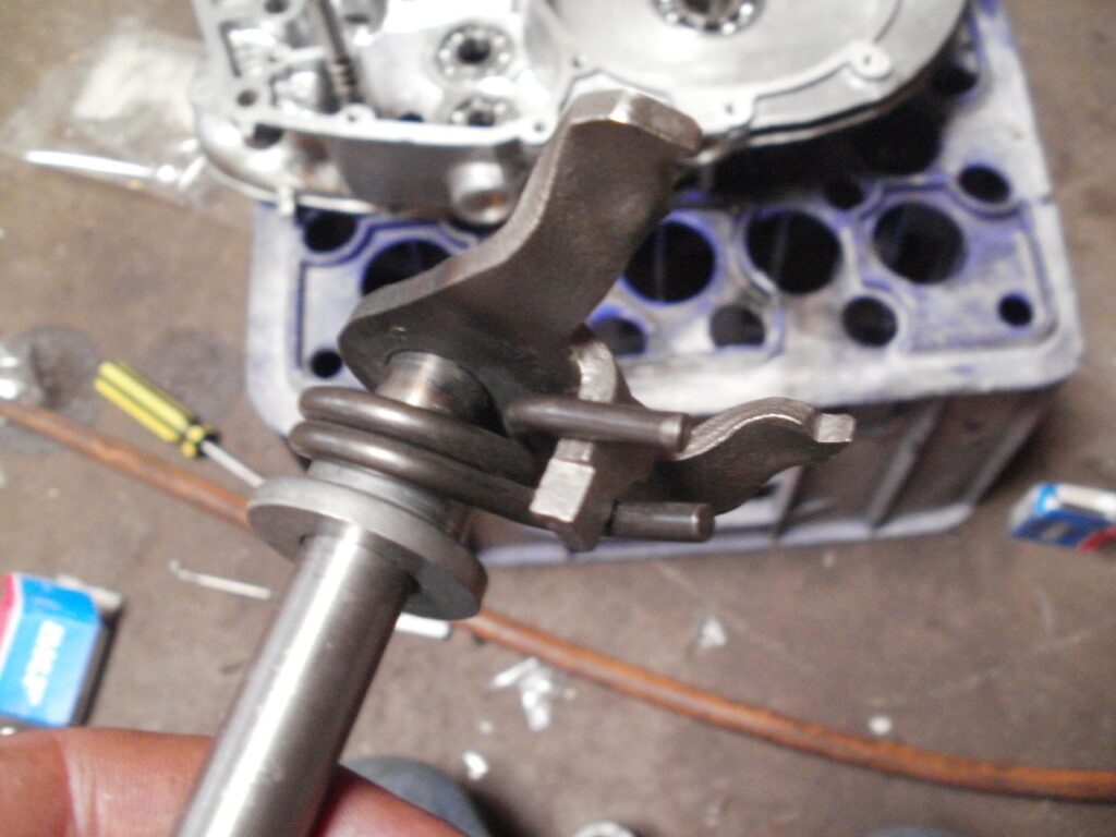
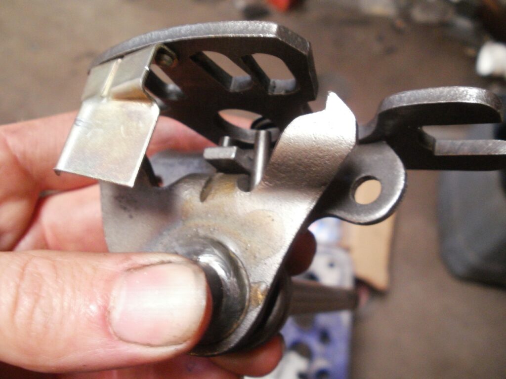
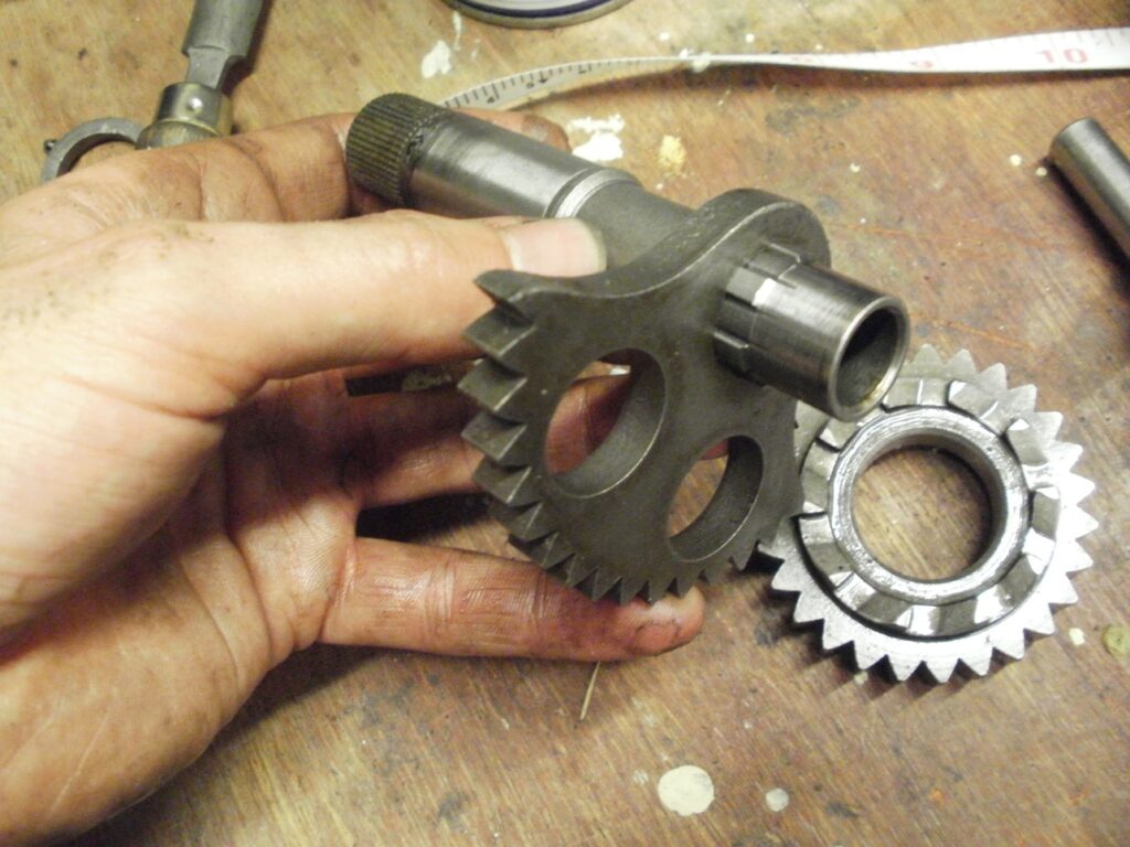
When I rebuilt the engine I noticed the layshaft and sliding gear had slightly rounded edges on the splines. I’ve seen worse, so reassembled it using the original components. Upon “second rebuild” it was clear I was being too optimistic. With the gearbox out of the crankcases, and the sliding gear in third gear position on the layshaft, I tried rotating the gear on the layshaft, and it was quite easy to get it to slip off the splines, thanks to the rounded edges. The layshaft has splines which are concave, which positively keep the sliding gear in place. In its current form, the gearbox was relying more on the selector to hold it in gear.
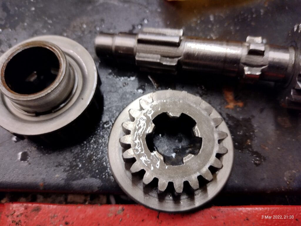
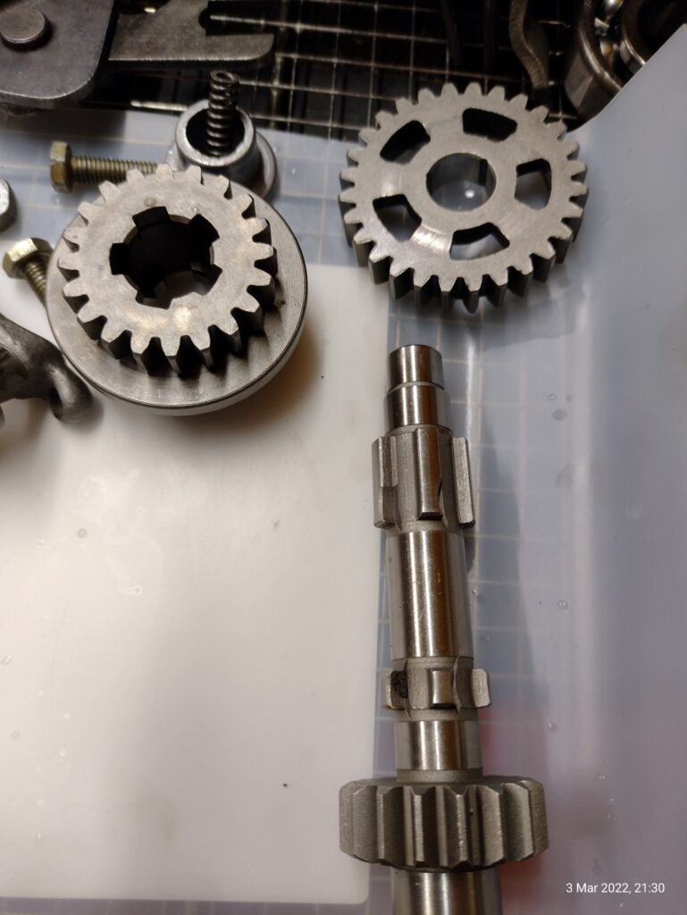
Fortunately, a sliding gear and layshaft was ordered cheaply from the continent (the UK spares market hasn’t improved of late –it was cheaper to buy from the continent and pay the understandably much higher postage, than to buy from the UK. Bizarre. Fortunately, up to £135, ordering stuff from elsewhere is very straightforward for the buyer. Some parts retailers were not sending to the UK, due to additional paperwork, which is fine, as other retailers were and I’m happy to take my custom elsewhere.
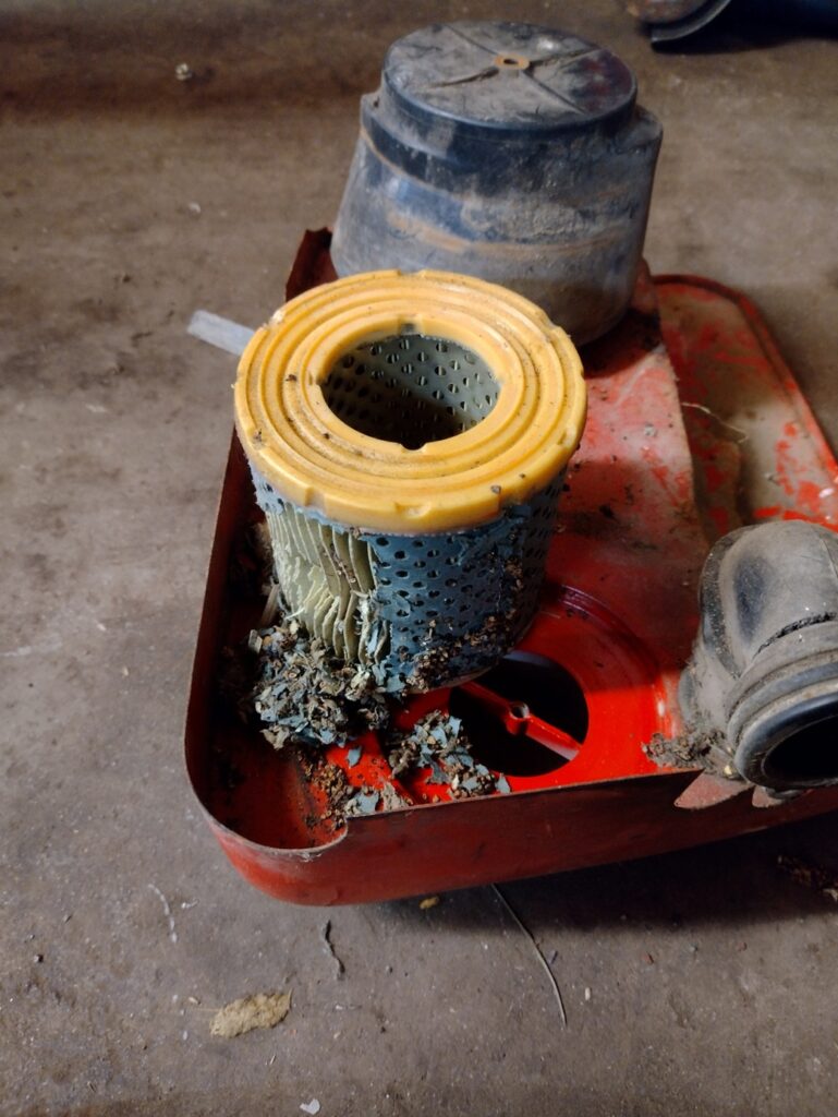
The engine remained in its disassembled state for several weeks whilst I finished off Uni coursework and exams (and work). In March I was able to finish the rebuild. Despite being completely clean upon reassembly some 40 miles ago, the crankcases were full of fibrous strands, which I can only assume was from the new air filter. It looked like manufacturing flash, and since the air box, intake rubber and carb were once spotless beforehand, I can see nowhere else this would’ve come from.
I’m not buying a new MZ-specific air filter again from the usual online marketplace, as these strands had almost made their way into the main bearings. Not far off oil starvation, as the main bearings rely solely on the drillings which take the oil/air mixture from the crankcase.

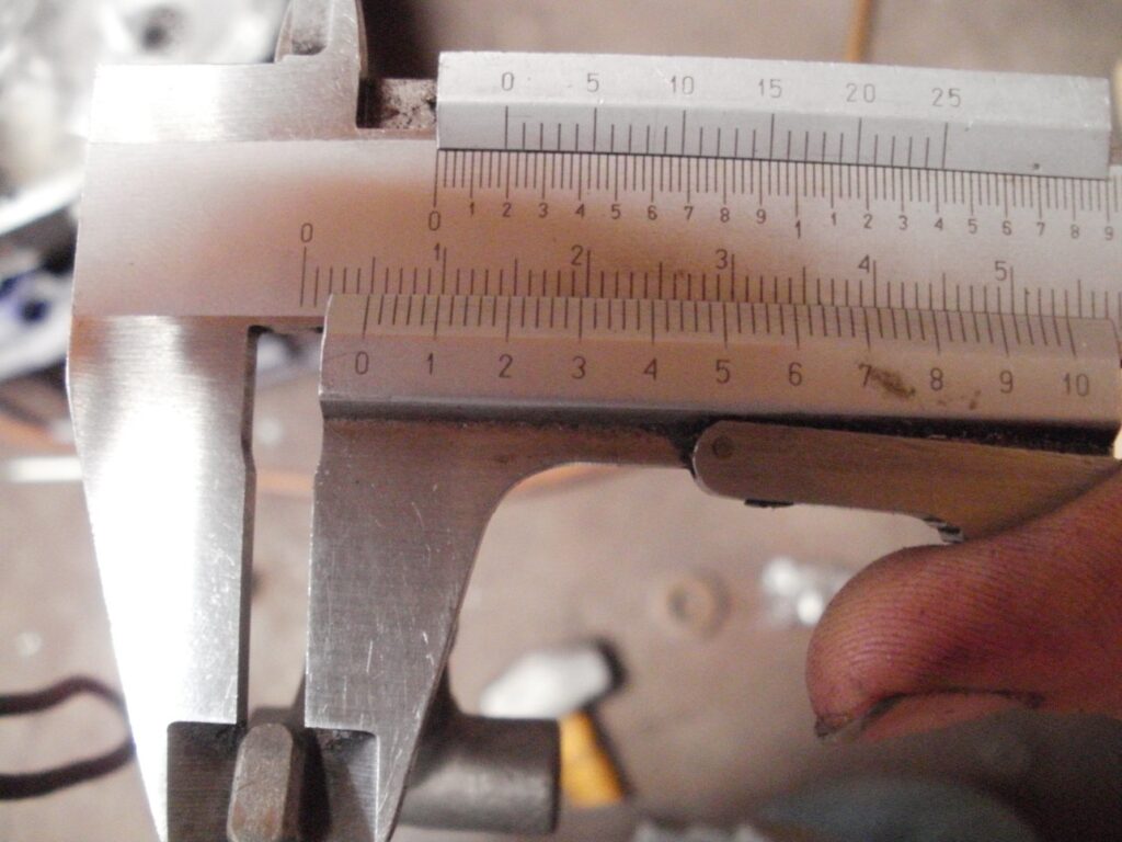
Everything was thoroughly cleaned and reassembled in the left crankcase, with new tab washers and the layshaft / sliding gear. I adjusted up the detent pin as per the manual. One important thing to note is that 2 distances (between sliding gear and 4th gear) are specified, 13mm in third gear and 0.2mm in 4th. I have never been able to achieve both of these settings, and the later supplement (from the 4th edition of the manual) recognises this. The 13mm measurement can be disregarded in favour of the 0.2mm. Effectively the 13mm relates to how the sliding gear sits on those concave splines. The 0.2mm measurement is the important one. Without this clearance, the gearbox bearings will be subject to axial loading in 4th gear. The ball bearings are not designed for such loading, and will fail over time. This 0.2mm allows for expansion.
The supplement says the 0.2mm clearance should also apply to the sliding gear on the layshaft, even if the 13mm third-gear measurement is no longer correct
The rebuild continued, as per the MZ manual.
It wasn’t until April when I finally got the engine reinstalled. Timing checked, and a new filter fitted off a stationary engine (though modified slightly to fit). The rattling noise from before had gone (likely as a result of adjusting everything again!)
I also treated the bike to a new shiny exhaust, making me even more scared of riding the bike and potentially dropping it! Having just done a 80mile round trip, the bike seems happy enough – running a little rich but will drop the needle down one once I’m happy it’s all run in. Starts easily enough, so it must be pretty close
I also fitted a 14 tooth sprocket, which is one tooth smaller than the standard TS125 gearing. Makes the bike very nice up to 45mph – starts to scream a bit above that. I’ve not yet gone over 6000 rpm, but it maintained a constant 50mph up a long and deceptively steep hill on the A38. I don’t do much dual carriageway work, where the 15 tooth setup is more suitable.
“Farewell”
Even at the start of the rebuild, I was considering selling the sport. As I stated earlier , it was probably too good to leave in the damp shed, or abuse it for commuting.
During summer 2022, the bike was listed online on a free advert. There was some interest, but not as much as I’d thought. I thought it was reasonably priced, considering it was a ready-to go bike, that was somewhat rare whilst being easy to buy parts for and easy to work on. An ideal entry classic, and all the other cliche’s sellers use.
Whilst waiting for the bike to sell, I finished a few things. I added new handlebars and replaced one of the switch gaitors. All minor stuff, but it makes a difference to the end result.
The switch gaitor was more problematic than I’d expected. Upon refitting the cover, I had both dipped and main beam constantly on. I fiddled about with the wires, then had the horn constantly on. I could see why this may be an issue, but managed to rectify it by adding some insulation to the “pass switch” contact (which turns on main beam) and refitting a replacement chrome cover. Later TS’s use plastic covers, which I can now see their benefit.
So far I have fitted 3 batteries to the machine, the two that failed were just down to lack of maintenance – really cheap batteries need to be charged up frequently, not left idle for months. This is why I like the cyclon batteries – they dont go flat for months, though unfortunately there’s no way of fitting 12v ones in the 125. By way of compromise, a sealed lead acid battery was fitted, and a charge lead for my old optimate for winter maintenance charging (without having to remove the side panel)
The bike sold end of august 2022, and at the time of writing is no longer in the shed. As part of the deal, I included a 6v setup, as well as one of the commerically-available 12v conversion kits albeit used and with a broken ignition coil.
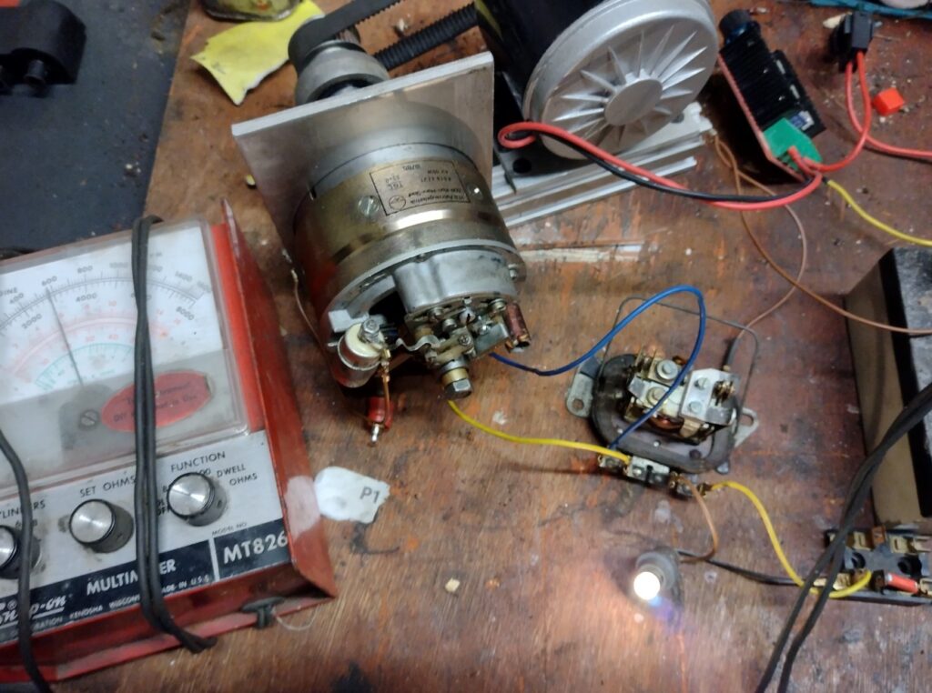
I wanted to make sure I wasnt including rubbish spares with the bike, so attached the dynamo and regulator to my test rig, and got 6.8v. So the regulator needs adjustment, but at least it proved it’s all working.
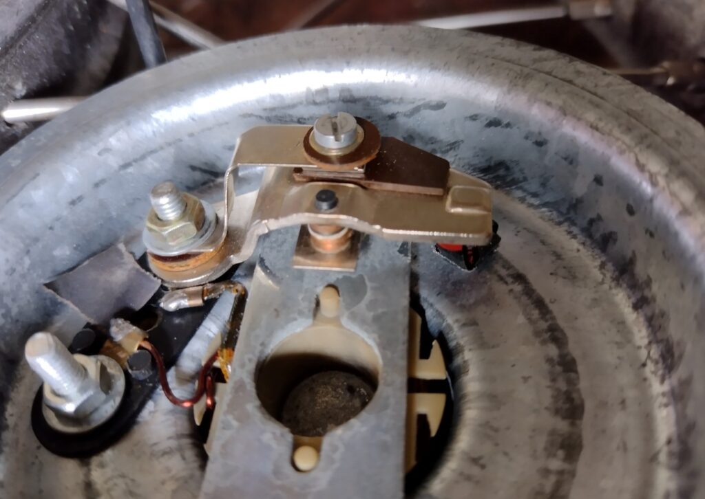
The 6v horn didnt work, and I’ve developed quite a collection of defunct MZ horns. I’ve been meaning to attempt a repair, so I thought this would be a good opportunity. The horn was the type with a pressed retaining ring, rather than rivetted. So it was just a case of slowly, with a screw driver, easing back the ring to remove the front cover.
Connecting the horn to 6v indicated no current draw, so it was likely the contacts being fouled up. Cleaning these with emery paper was enough to acheive continuity. Once I confirmed the electromagnet was working again, I refitted the front cover with some silicone sealant, and then clamped over the retaining ring again. End result wasnt pretty (I didnt clamp the ring well), but the horn worked well.
With all the spares sorted, and me happy with the bike, it was collected over the august bank holiday weekend. I’m glad to say it’s now with it’s new owner, who is rediscovering the wonderful world of MZ-ing.
Somewhat a bitter-sweet sale – a good amount of work gave me a bike far better than my usual commuting MZ, but that was the very reason I was OK with selling it. I knew if I’d kept it it wouldnt get used. Now, with space freed up in the shed, I can continue with the next bike – another MZ, though this time a tax expempt 150 in the “historic” tax class. That means free road tax, and combined with being a 150, a slightly more practical bike – ideal to ride to work.
There wont be any additional updates to this page – bet you’re glad, if you’ve read this far.