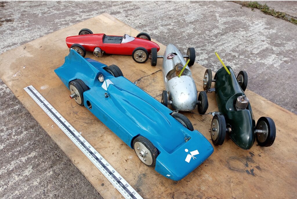
This page describes the build of a simple tethered car, using a lathe and a pillar drill. Not my own design, but my dad’s. The only credit I can claim is the CAD.
Below is Dad’s article, on how to build the car. Drawings and photographs are at the bottom of the page, too
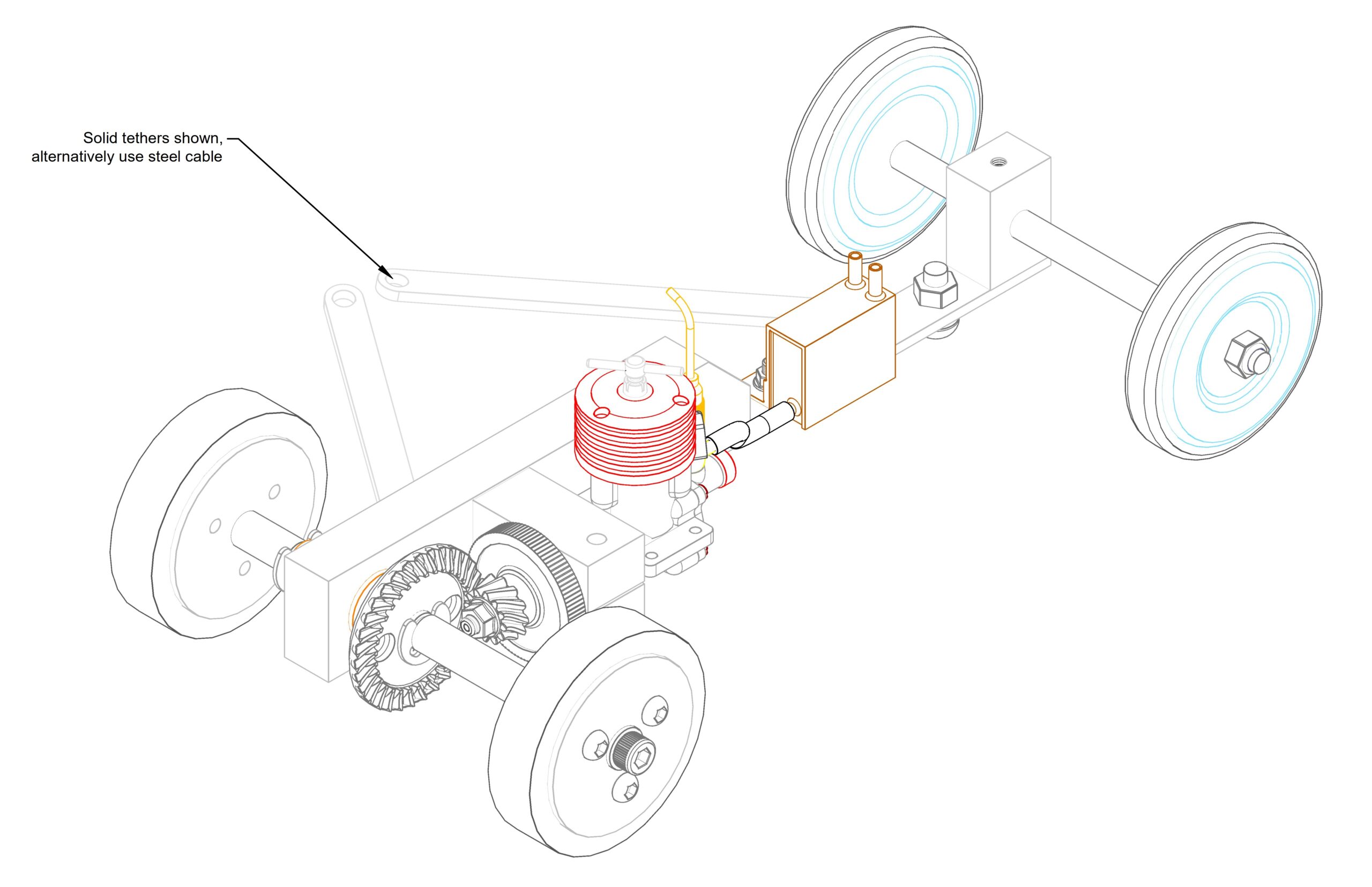
The chassis is based around the bevel gear set from a 4” angle grinder, and model diesel engine with rear induction (giving a parallel front crank case for ease of mounting) i.e. Russian MK17-rhytm 2.5-KDM-ED etc.
I have found that a geared drive system has the advantage of larger slower rotating wheels avoiding the necessity of vulcanised tyres. A geared engine is also much easier to push start.
The rolling chassis was designed to be built with minimum equipment: only a small lathe (three jaw chuck) and a pillar drill. The engine mounting housing and axle bush drillings were made with a reduced shank 5/8” blacksmith drill (available mail order for about £7), avoiding the use of boring bars or reamers.
New angle grinder gears are available from the internet (eBay or try useful&rare.com for dimensions) at very little cost (£6-12). For 1.5cc engines, the set from a 100mm angle grinder (with the pinion bore of 8mm) are required, and for 2.5cc engines (with the larger 6mm crankshaft), the gears from a 150mm angle grinder with 9 or 10mm pinion bore are best. There are many slight variations in gear ratios/size, so the dimensions on the drawings are only approximate. Please check with trial runs before cutting/drilling!
The Russian MK17 engine, although heavy for a model aircraft, is excellent for tethered car use. It is best to bench test-the engine, with a propeller fitted, to check all is well and have some basic settings for compression/needle valve before preparing for fitting to your car. The prop drive and collet should be removed as this will be replaced by the flywheel. The crankcase around the front bearing housing should be filed round and as parallel as possible.
The only parts requiring accurate machining are the flywheel and crankshaft collet. The flywheel is machined from 38mm (1.5”) EN1A mild steel or similar. Firstly machine down to suit your gear pinion (8mm diameter for MK17) and cut to length. Reverse in chuck, centre and drill to suit crankshaft (5mm for MK17). The internal taper for the collet should now be cut with a small boring bar (6mm tool steel, ground to suitable tip) with the top slide of your lathe set at 7˚. Remove the flywheel and mount a short piece of brass/bronze/aluminium in the chuck for your collet. Cut the external taper of the collet without resetting the top slide to ensure a good fit into the flywheel. The collet can then be drilled to suit your crankshaft, cut off and slot.
The engine block is a simple piece of aluminium (1 ¼” x ¾” stock, or similar) drilled (I used the 5/8” blacksmith drill as the reduced shank would fit in the small pillar drill) to suit your engine crankcase. Drill and tap for the clamp bolt before slotting. Note that the crankcase should have 2-3mm lateral movement in its mounting block to allow adjustment for gear mesh.
The main chassis rail (made from the same material as the engine block) may be the full length of the model or just a short “sub-frame” to be fitted to a floor casting/pan/extension plate. The hole for the axle bearing should be drilled (I used the 5/8” drill again) and the axle bearing made a press fit into the rail.
The next important job is to align the engine mounting block with the chassis rail. This is best done by temporarily fitting the crown gear to its axle bush with a 10mm (or to suit your crown wheel/bush) bolt. Place the engine mounting block (with engine/flywheel/pinion centrally clamped in place) on the rail with the gears meshing correctly. Scribe a line around the block so that when the block is removed two 3mm locating dowel holes can be drilled in the rail. The engine mounting block should then be temporarily held in place with 2 pack epoxy adhesive. The holes in the rail can then be used as a guide to drill the dowel holes in the engine mounting block. Finally fit 3mm dowel pins, and drill/tap for the main M8 fixing bolt.
The axle is a straight forward machining job, the drive for the crown wheel can either be a simple 3mm pin or if a milling machine is available, a slot maybe machined and a woodruff key used. Please note that the length of the axle, the position of the crown wheel and the size of the tyres will be dependent on the type and size of the model you are making.
Tyres are made from offcuts of reinforced industrial rubber sheeting. Staple the rubber sheet to a sacrificial block of wood, mounted to a pillar drill. Cut out the centre hole using a holesaw then without moving the drill centre line, cut out the outer diameter, again with a suitable size holesaw. The wheels can then be made to suit the tyres. The front wheels/tyres are made in a similar manner, but with the addition of an axle bush or bearing.
Assembly and running notes
A 1.5cc powered car will pull a car of approximately 1.6kg. A 2.5cc car approximately 2.7kg
The engine should face the outer side of the tethered circle and can be mounted vertically or horizontally
We have available laser-cut crankcase gaskets for the MK17
The crown wheel pinion meshing can be adjusted by moving the engine fore and aft in its mounting block and shim between the crown wheel and axle bush until they run smoothly
The fuel tank can be made from central heating copper end cap fittings, soldered each end to a short length of suitable copper pipe (15mm for 1.5cc engines, 22mm for 2.5cc engines)
The tethered cable bridle mounting should be at the balance point of the car. I have found the best method is to use mounting points at both ends of the chassis rail and use two cables which can be adjusted in length until the car tracks correctly.
On the first push starts, the crankshaft nut WILL work loose. Tighten and retry several times until the flywheel/collet settles in, then glue with locktite and will then hold.
Body shell design and type can be made from wood glass fibre or aluminium at your discretion.